Page 606 - Subyek Computer Aided Design - [David Planchard] Engineering Design with SOLIDWORKS
P. 606

Top-Down and Sheet Metal Parts                                                                                                                             Engineering Design with SOLIDWORKS® 2018


                                                Display the Sheet Metal toolbar.


                                                217) Click View, Toolbars from the Main menu.                                                                                                                                                                                            ~ Selection Filter


                                                                                                                                                                                                                                                                                         D  Sheet  Format
                                                218) Check Sheet Metal. The Sheet Metal toolbar is displayed.

                                                                                                                                                                                                                                                                                         en  S l_eet  Metal


                                                                                                                                                                                                                                                                                         C  S~ch
                                                219) Click and drag to a location inside the Graphics window.


                                                   , ,/


                                                  -;Q::.  Maintain constant thickness. Sheet metal features only work with constant wall


                                                thickness. The Shell feature maintains constant wall thickness. The solid Extruded Base


                                                feature represents the overall size of the sheet metal CABINET. The CABINET part is


                                                solid. The Rip feature and Insert Sheet Metal Bends feature convert a shelled solid part


                                                into a sheet metal part.


                                                CABINET-Rip Feature and Sheet Metal Bends


                                                The Rip feature creates a cut of no thickness along the edges
                                                                                                                                                                                                                                                                                                                                II


                                                of the Extruded Base feature. Rip the Extruded Base feature                                                                                                                                                   ~~                       ~                         ~ ~~
                                                                                                                                                                                                                                                                              Ill

                                                along the four edges. The Bend feature creates sheet metal                                                                                                                                                     Rip


                                                bends.                                                                                                                                                                                                         Creates a gap between two edges in

                                                                                                                                                                                                                                                               a sheet metal part.
                                                                                                                                                                                                                                                                                                                                  I


                                                Specify bend parameters: bend radius, bend allowance and relief. Select the bottom face


                                                to remain fixed during bending and unbending. In the next example, you will create the


                                                Rip and the Insert Bend features in two steps. The Bends PropertyManager contains the


                                                Rip parameter. Utilize the Rip feature to create a simple Rip and Bend in a single step.


                                                I Activity: CABINET-Rip Feature and Sheet Metal Bends


                                                Fit the model to the Graphics window.


                                                220) Press the f key.


                                                Insert a Rip feature. A Rip feature creates a gap between two edges in a


                                                sheet metal part.


                                                221) Click Rip ~ from the Sheet Metal tool bar. The Rip


                                                                 PropertyManager is displayed.


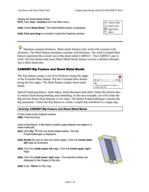
                                                222) Rotate the part to view the inside edges. Click the inside lower


                                                                 left edge as illustrated.


                                                223) Click the inside upper left edge. Click the inside upper right


                                                                 edge.


                                                224) Click the inside lower right edge. The selected entities are


                                                                 displayed in the Edges to Rip box.
                                                                                                                                                                                                                                                                                                                           ,

                                                                                                                                                                                                                                                                                                                                 •
                                                                                                                                                                                                                                                                                                         ~       --..I,- r

                                                225) Enter .1 Omm for Rip Gap.


                                                                                                                                                                                PAGE 7 - 40
   601   602   603   604   605   606   607   608   609   610   611