
Page 609 - Subyek Computer Aided Design - [David Planchard] Engineering Design with SOLIDWORKS
P. 609
Engineering Design with SOLIDWORKS® 2018 Top-Down and Sheet Metal Parts
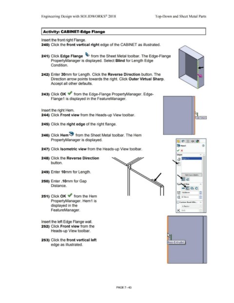
I Activity: CABINET-Edge Flange
Insert the front right Flange.
240) Click the front vertical right edge of the CABINET as illustrated.
241) Click Edge Flange ~ from the Sheet Metal tool bar. The Edge-Flange
PropertyManager is displayed. Select Blind for Length Edge
Condition.
242) Enter 30mm for Length. Click the Reverse Direction button. The
Direction arrow points towards the right. Click Outer Virtual Sharp.
Accept all other defaults.
243) Click OK ~ from the Edge-Flange PropertyManager. Edge-
Flange1 is displayed in the FeatureManager.
Insert the right Hem.
244) Click Front view from the Heads-up View toolbar.
Edge-Flange 1
245) Click the right edge of the right flange.
246) Click Hem 8 from the Sheet Metal tool bar. The Hem
PropertyManager is displayed. ~ ~ll'3 $~
8 Hem1 (1)
247) Click Isometric view from the Heads-up View toolbar. ~ x
Edges "' ~
248) Click the Reverse Direction Ed e<1>
button.
249) Enter 1 Omm for Length.
Edit Hem Width
250) Enter .1 Omm for Gap
Distance.
G:! ~ ~~
~ 110.oomm ,~
251) Click OK .; from the Hem @. lo.1omm !g
PropertyManager. Hem 1 is O Custom Bend Allo... "'
displayed in the K-Factor
FeatureManager. K o.4s
Insert the left Edge Flange wall.
252) Click Front view from the
Heads-up View toolbar.
253) Click the front vertical left
Boss-Extrude 1
edge as illustrated.
PAGE? - 43