
Page 607 - Subyek Computer Aided Design - [David Planchard] Engineering Design with SOLIDWORKS
P. 607
Engineering Design with SOLIDWORKS® 2018 Top-Down and Sheet Metal Parts
226) Click OK~ from the Rip PropertyManager. Rip1 is displayed in the
·c::s;J ~ LffB ~ I "'
FeatureManager.
$ Rip G)
Rip Parameters
Insert the Sheet Metal Bends.
Ii:) Edge<1>
227) Click the inside bottom face to remain fixed. Edge<2>
Edge<3>
•
228) Click Insert Bends ~ from the Sheet Metal toolbar. The Bends I Change DirectioiJ
PropertyManager is displayed. Face<1 > is displayed. ,t 1.,omm I :
229) Enter 2.00mm for Bend radius.
~l~ l~:$ 1
230) Enter .45 for K-Factor. Enter .5 for Rectangular Relief. .a Bends
~ x
231) Click OK~ from the Bends PropertyManager. Bend Parameters
-----------
Face<1 >
232) Click OK to the message, "Auto relief cuts were made for one or -------,-l Bend Radius I:!
more bends." ~ 2.00mml
~ O.OOin
f.;;,,,.~
~ [21 Ignore beveled faces
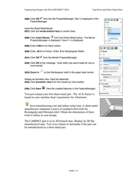
233) Zoom in on the Rectangular relief in the upper back corner.
Bend Allowance A
K-Factor vJ
Display an Isometric view. Save the assembly. 1
K o.4s 1:1
234) Click Isometric view from the Heads-up View toolbar.
G2I Auto Relief A
v]
Rectangular
235) Click Save ~ . View the created features in the FeatureManager. I o.s I:
You just created your first sheet metal part. The .45 K-Factor is Rip Parameters v
based on your machine shop's parameters for Aluminum.
, ,/
-;Q~ Save manufacturing cost and reduce setup time. A sheet metal
manufacturer maintains a turret of standard relief tools for
Rectangular and Obround relief. Obtain the dimensions of these
tools to utilize in your design.
The CABINET part is in its 30 formed state. Display its 2D flat
manufactured state. Test every feature to determine if the part can
be manufactured as a sheet metal part.
PAGE 7 - 41