
Page 603 - Subyek Computer Aided Design - [David Planchard] Engineering Design with SOLIDWORKS
P. 603
Engineering Design with SOLIDWORKS® 2018 Top-Down and Sheet Metal Parts
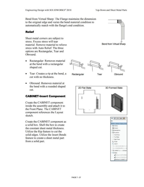
Bend from Virtual Sharp: The Flange maintains the dimension
to the original edge and varies the bend material condition to
automatically match with the flange's end condition.
Relief
Sheet metal comers are subject to
stress. Excess stress will tear i
material. Remove material to relieve Bend from Virtual Sharp
stress with Auto Relief. The three
options are Rectangular, Tear and
Obround.
• Rectangular: Removes material
at the bend with a rectangular
shaped cut.
• Tear: Creates a rip at the bend, a Rectangular Tear Obround
cut with no thickness.
• Obround: Removes material at
the bend with a rounded shaped
20 Flat State 30 Formed State
cut.
CABINET-Insert Component
~
a
D
D
Create the CABINET component D
a
D .
D •
inside the assembly and attach it to D
D
D
D
D
the Front Plane. The CABINET • • •
component references the Layout • •
sketch.
Create the CABINET component as
(!) BOX (Default< Display State·
a solid box. Shell the box to create • ~ History
the constant sheet metal thickness. l'srJ Sensors
• [A) Annotations
Utilize the Rip feature to cut the
• ll'.) Equations
solid edges. Utilize the Insert Bends (!) Front Plane
feature to create a sheet metal part CJ Top Plane
(;] Right Plane
from a solid part. L Origin
L. Layout
(1J {·) MOTHERBOARD<!> (I
('~ {·) POWERSUPPLY<l> (D1
• (S:, CABINET <l > ·> (Default•
• @@ Mates
~ InPlacel (MOTHERBO,
~ InPlace2 (POWERSUPP
~ lnPlace3 (CABINET <l )
PAGE? - 37