
Page 598 - Subyek Computer Aided Design - [David Planchard] Engineering Design with SOLIDWORKS
P. 598
Top-Down and Sheet Metal Parts Engineering Design with SOLIDWORKS® 2018
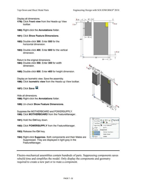
Display all dimensions.
-I
25 -
· 20 - ~ -t _J_
179) Click Front view from the Heads-up View I ..., -
1l
tool bar. t 20 - ~ : 20
I ~
180) Right-click the Annotations folder.
I
181) Click Show Feature Dimensions. -~
l-7s-,
400
182) Double-click 300. Enter 550 for the
horizontal dimension.
183) Double-click 400. Enter 600 for the vertical
~
dimension. - 20
- I
I
I ·~
- 300 I
Return to the original dimensions.
184) Double-click 550. Enter 300 for width
dimension.
185) Double-click 600. Enter 400 for height dimension.
Display an Isometric view. Save the assembly.
186) Click Isometric view from the Heads-up View toolbar.
187) Click Save liii.
Hide all dimensions.
188) Right-click the Annotations folder.
189) Un-check Show Feature Dimensions.
Suppress the MOTHERBOARD and POWERSUPPL Y.
190) Click MOTHERBOARD from the FeatureManager.
191) Hold the Ctrl key down. • Efl Equations ~
(P Front Plan e, ~ ' "- ® ID ~ ~ Im
. fe··~
(P Top Plane , Suppress
192) Click POWERSUPPL Y from the FeatureManager. (P Right Plan ~ Invert Selection
L Origin Go To ...
C Layout Component
193) Release the Ctrl key. • ~ MOTHERB Hidden Tree Items •
• ~ POWERSU Make Virtual
194) Right-click Suppress. Both components and their Mates are • ®~ Mates lsolate
-
Suppressed. They are displayed in light gray in the
FeatureManager.
Electro-mechanical assemblies contain hundreds of parts. Suppressing components saves
rebuild time and simplifies the model. Only display the components and geometry
required to create a new part or to mate a component.
PAGE? - 32