
Page 593 - Subyek Computer Aided Design - [David Planchard] Engineering Design with SOLIDWORKS
P. 593
Engineering Design with SOLIDWORKS® 2018 Top-Down and Sheet Metal Parts
133) Click Convert Entities © from the Sketch toolbar.
134) Drag the bottom end point of the converted line three quarters
upward.
135) Drag the left end point of the converted line three quarters of the
way to the right. Click Front view from the Heads-up View toolbar.
136) Click Line / from the Sketch toolbar.
137) Sketch a vertical line as illustrated.
138) Sketch a horizontal line to complete the rectangle.
Add dimensions.
139) Click Smart Dimension <' from the Sketch toolbar.
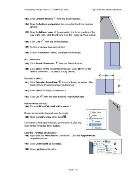
140) Enter 30mm for the horizontal dimension. Enter 50mm for the
vertical dimension. The sketch is fully defined.
Extrude the sketch.
141) Click Extruded Boss/Base ~ from the Features toolbar. The
Boss-Extrude PropertyManager is displayed. 50
142) Enter 1 Omm for Depth in Direction 1.
143) Click OK if from the Boss-Extrude PropertyManager.
Rename Boss-Extrude2.
144) Rename Boss-Extrude2 to Connector1.
Display an Isometric view and save the model. Q Right Plane
145) Click Isometric view. Click Save l'i. L Origin
.-
• ~ Base Extrude - >
Use color to indicate electrical connectors. Color the L Sketch1 ->
·-
face of the Extruded Boss feature. • I~ Connector1 j
L Sketch2
Color the Front face of Connector1.
146) Right-click the Front face of Connector1. Click the Appearances
drop-down arrow.
1$~ ~ 10 +,
147) Click Connector1 as illustrated. ~ e=. <~ fe! r
~ Face<1 > ...
Selection Too ~
~ Connecto ... ..._
148) Select yellow as the color. Zoom/ Pan/ Roi ~ Body • "°
~ MOTHE... 0
Recent Com!
PAGE? - 27