
Page 588 - Subyek Computer Aided Design - [David Planchard] Engineering Design with SOLIDWORKS
P. 588
Top-Down and Sheet Metal Parts Engineering Design with SOLIDWORKS® 2018
Select the BOX assembly Front Plane to create InPlace Mates. An InPlace Mate is a
Coincident Mate developed between the Front Plane of the component and the selected
plane in the assembly. Utilize Convert Entities and extract geometry from the Layout
Sketch to create external references for both the MOTHERBOARD part and
POWERSUPPL Y part. Utilize Ctrl-Tab to switch between part and assembly windows.
MOTHERBOARD-Insert Component
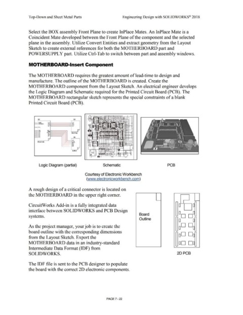
The MOTHERBOARD requires the greatest amount of lead-time to design and
manufacture. The outline of the MOTHERBOARD is created. Create the
MOTHERBOARD component from the Layout Sketch. An electrical engineer develops
the Logic Diagram and Schematic required for the Printed Circuit Board (PCB). The
MOTHERBOARD rectangular sketch represents the special constraints of a blank
Printed Circuit Board (PCB).
,:,
,;,
X.2 X3
0
•
.
•eser ADC ADC
W,.TCHDOG N3C AGC
SUfJ suu ..
P1D P1D .,
)
""' ,:
1)(0 l fTI I/ -tt-+' ,•
,uu,
l!XD ~ '
"' RELAY Anal.og
,,.
,12
DA1
~··
' ;,
... DA2 X6 ~
"'
'"
,
I/ .1•"1tt' .
INTI
Di1Ji t al. Pun,
RE:IAY
DA1
,,.
DA2
I/
0 ,:, 0 ,:, ,:, ,:,
InOut
u,.
Logic Diagram (partial) Schematic PCB
Courtesy of Electronic Workbench
(www.electronicworkbench.com)
A rough design of a critical connector is located on
the MOTHERBOARD in the upper right comer.
~ -
CircuitWorks Add-in is a fully integrated data o~oo
interface between SOLIDWORKS and PCB Design
Board ~ OD Do=
systems.
Outline 0 0
As the project manager, your job is to create the OD Do
board outline with the corresponding dimensions - -
~ oD Do-
from the Layout Sketch. Export the
MOTHERBOARD data in an industry-standard OD DD
- -
Intermediate Data Format (IDF) from
SOLID WORKS. 2DPCB
The IDF file is sent to the PCB designer to populate
the board with the correct 2D electronic components.
PAGE? - 22