
Page 587 - Subyek Computer Aided Design - [David Planchard] Engineering Design with SOLIDWORKS
P. 587
Engineering Design with SOLIDWORKS® 2018 Top-Down and Sheet Metal Parts
Additional dimensions are required for Equations. Each dimension has a unique variable
name. The names are used as Equation variables. The default names are based on the
Sketch, Feature or Part. Feature names do not have to be changed. Rename variables for
clarity when creating numerous Equations.
Rename the BOX assembly width and height. The full variable name is ''box-width@
Layout.'' The system automatically appends Layout. If features are created or deleted in a
different order, your variable names will be different.
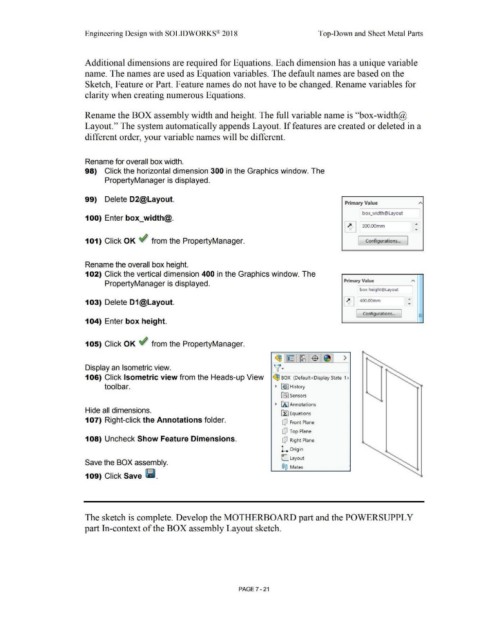
Rename for overall box width.
98) Click the horizontal dimension 300 in the Graphics window. The
PropertyManager is displayed.
99) Delete D2@Layout.
Primary Value
box_width@Layout
100) Enter box_width@.
~ 300.00mm ,..
101) Click OK ~ from the PropertyManager. [ Configurations... ]
Rename the overall box height.
102) Click the vertical dimension 400 in the Graphics window. The
Primary Value
PropertyManager is displayed.
box height@Layout
103) Delete D1@Layout. ~ 400.00mm
-
Configurations... J -
-
104) Enter box height.
105) Click OK ~ from the PropertyManager.
~1~ 1~1$ 1~1 >
v·
Display an Isometric view.
106) Click Isometric view from the Heads-up View ~ BOX (Default <Display State-1 >
tool bar. • ~I History
~ Sensors
• IA I Annotations
Hide all dimensions.
Efl Equations
107) Right-click the Annotations folder. dJ Front Plane
dJ Top Plane
108) Uncheck Show Feature Dimensions. dJ Right Plane
l. Origin
C Layout
Save the BOX assembly.
®@ Mates
109) Click Save Iii.
The sketch is complete. Develop the MOTHERBOARD part and the POWERSUPPL Y
part In-context of the BOX assembly Layout sketch.
PAGE? - 21