
Page 592 - Subyek Computer Aided Design - [David Planchard] Engineering Design with SOLIDWORKS
P. 592
Top-Down and Sheet Metal Parts Engineering Design with SOLIDWORKS® 2018
Return to the BOX assembly.
123) Click Edit Component ~ from the Assembly toolbar. The
FeatureManager is displayed in black. Rebuild the model.
Fit and Save the BOX to the Graphics window.
124) Press the f key. Click Save lii.
125) Click Save All to save all modified documents.
126) Click OK to Save internally (inside the assembly).
~
I d~ l ~ ~~ irn
I" ' ~ "' ®
- ~
-
Save and rename the default virtual component [Part1 "BOX]<#> -> to ~ Open Part
MOTHERBOARD. ~
Invert Selection
127) Right-click [ Part1 ABOX ]<#> ->. Click Open Part. Go To ...
Component (Part1 "'BOX)
128) Click Save As from the Menu bar. Click OK from the dialog
box. (93 ~~ $~ >
)[·
129) Enter MOTHERBOARD in the File name box. Note: Save in the (93 BOX (Default<Display State "'
VENDOR-COMPONENTS folder. Click Save as. Click Save. Close • [€} J History
the MOTHERBOARD part. Return to the BOX assembly. View the lflJ Sensors
updated FeatureManager. • fA"l Annotations
• ll:] Equations
dJ Front Plane
The Reference models are the MOTHERBOARD and the BOX
dJ Top Plane
assembly. Additional features are required that do not reference the dJ Right Plane
Layout Sketch or other components in the BOX assembly. An l. Origin
Extruded Boss feature indicates the approximate position of an L Layout
"' ~ MOTHERBOARD <2> - >
electrical connector. The actual measurement of the connector or
• ~ Mates in BOX
type of connector has not been determined. • IJ9 I History
~ Sensors
Perform the following steps to avoid unwanted assembly references: • [A] Annotations
~ Equations
o-
::o Material <not speci
1. Open the part from the assembly. 2. Add features. 3. Save the
dJ Front Plane
part. 4. Return to the assembly. 5. Save the assembly. dJ Top Plane
dJ Right Plane
l. Origin
Insert an Extruded Boss/Base feature for the MOTHERBOARD.
.-
.... ~ Base Extrude - > -
130) Right-click MOTHERBOARD in the FeatureManager. L Sketch1 ->
131) Click Open Part. The MOTHERBOARD FeatureManager is
displayed. Press the f key.
Insert the Sketch.
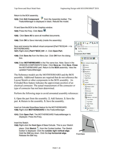
132) Right-click the front face of Base Extrude. This is your Sketch
o-
plane. Click Sketch L from the Context toolbar. The Sketch
toolbar is displayed. Click the outside right vertical edge.
Hold the Ctrl key down. Click the top horizontal edge.
Front face
Release the Ctrl key.
PAGE? - 26