Page 595 - Subyek Computer Aided Design - [David Planchard] Engineering Design with SOLIDWORKS
P. 595

Engineering Design with SOLIDWORKS® 2018                                                                                                                                                          Top-Down and Sheet Metal Parts


                                                                        Select the Sketch plane.                                                                                                                                                                                              ~ ,·~ ,·~: $: ~,                                               >


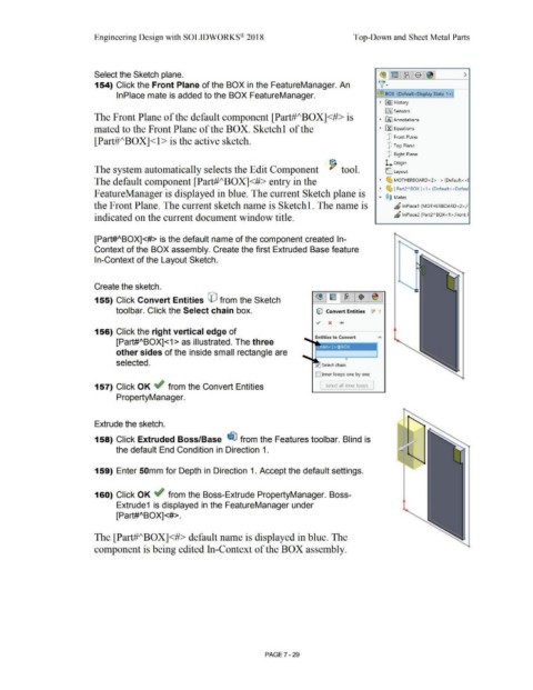
                                                                        154) Click the Front Plane of the BOX in the FeatureManager. An                                                                                                                                                      ~ ·


                                                                                        lnPlace mate is added to the BOX FeatureManager.                                                                                                                                                    ~ BOX  (Default<Display State-1 >}

                                                                                                                                                                                                                                                                                              •   ~ I History


                                                                                                                                                                                                                                                                                                  lfi] Sensors
                                                                        The Front Plane of the default component [Part#J\BOXJ<#> is                                                                                                                                                           •   IA] Annotations


                                                                        mated to the Front Plane of the BOX. Sketchl of the                                                                                                                                                                   •   El::! Equations


                                                                                                                                                                                                                                                                                                   [P  Front Plane
                                                                        [Part#ABOX]<l > is the active sketch.

                                                                                                                                                                                                                                                                                                   [P  Top Plane


                                                                                                                                                                                                                                                                                                   [P  Right Plane


                                                                                                                                                                                                                                                                                                  L  Origin
                                                                        The system automatically selects the Edit Component  '  tool.                                                                                                                                                              (:_ Layout


                                                                        The default component [Part#ABOXJ<#> entry in the                                                                                                                                                                     •    ~ MOTHERBOARD<2> -> (Default<<I

                                                                                                                                                                                                                                                                                              •    ~ [ Part2"80X]<1> (Default<<Defaul

                                                                       F eatureManager is displayed in blue_ The current Sketch plane is                                                                                                                                                      ....   @ij  Mates


                                                                        the Front Plane. The current sketch name is Sketchl. The name is                                                                                                                                                                 "' lnPlace1  (MOTHERBOARD<2>,F


                                                                        indicated on the current document window title.                                                                                                                                                                                  "     lnPlace2 (Part2" 80X<1>,Front F


                                                                        [Part#ABOX]<#> is the default name of the component created In-


                                                                        Context of the BOX assembly. Create the first Extruded Base feature


                                                                        In-Context of the Layout Sketch.


                                                                        Create the sketch.


                                                                        155) Click Convert Entities CO from the Sketch


                                                                                        toolbar. Click the Select chain box.                                                                                                                   lfj Convert Entities  JI  ·,


                                                                        156) Click the right vertical edge of


                                                                                        [Part#ABOX]<1 > as illustrated. The three


                                                                                        other sides of the inside small rectangle are


                                                                                        selected.


                                                                                                                                                                                                                                             ID Inner loops one by one


                                                                        157) Click OK ~ from the Convert Entities                                                                                                                                [  Select all inner loops  ]


                                                                                        PropertyManager.


                                                                        Extrude the sketch.


                                                                        158) Click Extruded Boss/Base  ~ from the Features toolbar. Blind is


                                                                                        the default End Condition in Direction 1.


                                                                        159) Enter 50mm for Depth in Direction 1. Accept the default settings.


                                                                        160) Click OK ~ from the Boss-Extrude PropertyManager. Boss-


                                                                                        Extrude1  is displayed in the FeatureManager under


                                                                                        [Part#ABOX]<#>.


                                                                        The [Part#ABOXJ<#> default name is displayed in blue. The


                                                                        component is being edited In-Context of the BOX assembly.


                                                                                                                                                                                                        PAGE ?-29
   590   591   592   593   594   595   596   597   598   599   600