Page 596 - Subyek Computer Aided Design - [David Planchard] Engineering Design with SOLIDWORKS
P. 596

Top-Down and Sheet Metal Parts                                                                                                                             Engineering Design with SOLIDWORKS® 2018


                                                Return to the BOX assembly.


                                                161) Click Edit Component  ~ from the Assembly toolbar. The


                                                                 [Part#ABOX]<#> displayed in black.


                                                Save the BOX assembly.


                                                162) Click Savellj. Click Save All. Click OK to save internally.


                                                Rename the default component [Part2ABOX]<1 > to POWERSUPPL Y.


                                                163) Right-click [ Part#ABOX ]<1> ->. Click Open Part.


                                                                The [Part#ABOX ]<1 > -> FeatureManager is displayed.


                                                164) Click Save As from the Menu bar. Enter POWERSUPPL Y in the                                                                                                                                                                                                                      >


                                                                 File name box. Save in the VENDOR-COMPONENTS folder.


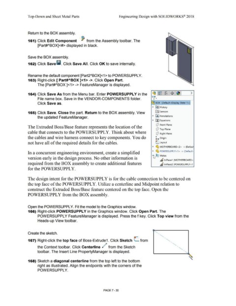
                                                                Click Save as.                                                                                                                                                                                    c!!fJ  BOX  (Default<Display State- 1 >)


                                                                                                                                                                                                                                                                    ~  ~ ] History


                                                165) Click Save. Close the part. Return to the BOX assembly. View                                                                                                                                                        (fl] Sensors


                                                                the updated FeatureManager.                                                                                                                                                                         ~  00 Annotations


                                                                                                                                                                                                                                                                    ~  ll] Equations


                                                                                                                                                                                                                                                                          (P  Front Plane
                                                The Extruded Boss/Base feature represents the location of the


                                                                                                                                                                                                                                                                          (P  Top Plane
                                                cable that connects to the POWERSUPPL Y. Think about where                                                                                                                                                                [P  Right Plane


                                                the cables and wire harness connect to key components. You do                                                                                                                                                            l.. Origin


                                                not have all of the required details for the cables.                                                                                                                                                                     L      Layout


                                                                                                                                                                                                                                                                    ~  ~ MOTHERBOARD<2> -> (Defaul'


                                                In a concurrent engineering environment, create a simplified                                                                                                                                                        ~  ~ POWERSUPPLY<1 > -> (Default·


                                                                                                                                                                                                                                                                   ~ ®@  Mates
                                                version early in the design process. No other information is

                                                                                                                                                                                                                                                                                "       lnPlace1  (MOTHERBOARD<

                                                required from the BOX assembly to create additional features                                                                                                                                                                    "       lnPlace2 (POWERSUPPLY < 1


                                                for the POWERSUPPLY.


                                                The design intent for the POWERSUPPL Y is for the cable connection to be centered on


                                                the top face of the POWERSUPPL Y. Utilize a centerline and Midpoint relation to


                                                construct the Extruded Boss/Base feature centered on the top face. Open the


                                                POWERSUPPLY from the BOX assembly.


                                                Open the POWERSUPPL Y. Fit the model to the Graphics window.


                                                166) Right-click POWERSUPPLY in the Graphics window. Click Open Part. The


                                                                 POWERSUPPL Y FeatureManager is displayed. Press the f key. Click Top view from the


                                                                 Heads-up View toolbar.


                                                Create the sketch.                                                                                                                                                                                                           '


                                                                                                                                                                                                                                    o-


                                                167) Right-click the top face of Boss-Extrude1. Click Sketch L  from


                                                                                                                                                                                  ~p

                                                                the Context toolbar. Click Centerline  r1~  from the Sketch


                                                                toolbar. The Insert Line PropertyManager is displayed.


                                                168) Sketch a diagonal centerline from the top left to the bottom


                                                                 right as illustrated. Align the endpoints with the corners of the


                                                                 POWERSUPPL  Y.


                                                                                                                                                                                PAGE? - 30
   591   592   593   594   595   596   597   598   599   600   601