
Page 597 - Subyek Computer Aided Design - [David Planchard] Engineering Design with SOLIDWORKS
P. 597
Engineering Design with SOLIDWORKS® 2018 Top-Down and Sheet Metal Parts
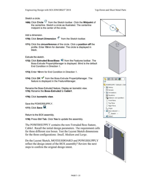
Sketch a circle.
..
169) Click Circle 0 from the Sketch toolbar. Click the Midpoint of
..
the centerline. Sketch a circle as illustrated. The centerline
midpoint is the center of the circle. a
..
Add a dimension.
170) Click Smart Dimension (' from the Sketch toolbar.
171) Click the circumference of the circle. Click a position off the
profile. Enter 15mm for diameter. The circle is displayed in
black.
Extrude the sketch.
172) Click Extruded Boss/Base ~ from the Features toolbar. The
Boss-Extrude PropertyManager is displayed. Blind is the default
End Condition in Direction 1.
173) Enter 1 Omm for End Condition in Direction 1.
174) Click OK ~ from the Boss-Extrude PropertyManager. The ~ E ~ -$ ~ >
feature is displayed in the FeatureManager. )[
~ POWERSUPPLY (Default <<Defc
~ ~ I History
Rename the Boss-Extrude2 feature. Display an Isometric view.
iftJ Sensors
175) Rename the Boss-Extrude2 to Cable1.
~ liAJ Annotations
[fJ Equations
176) Click Isometric view. o-
::e Material <not specified>
dJ Front Plane
Save the POWERSUPPL Y. dJ Top Plane
dJ Right Plane
177) Click Save l11. L Origin
• dJ:I Boss-Extrude1 ->
L_ Sketch1 ->
Return to the BOX assembly.
~ dIJ Cable1
178) Press Ctrl Tab. Click Yes to update the assembly.
The POWERSUPPL Y contains the new Extruded Boss feature,
Cable 1. Recall the initial design parameters. The requirement calls
for three different size boxes. Test the Layout Sketch dimensions
for the three configurations: Small, Medium and Large.
Do the Layout Sketch, MOTHERBOARD and POWERSUPPL Y
reflect the design intent of the BOX assembly? Review the next
steps to confirm the original design intent.
PAGE 7 -31