
Page 599 - Subyek Computer Aided Design - [David Planchard] Engineering Design with SOLIDWORKS
P. 599
Engineering Design with SOLIDWORKS® 2018 Top-Down and Sheet Metal Parts
,, /
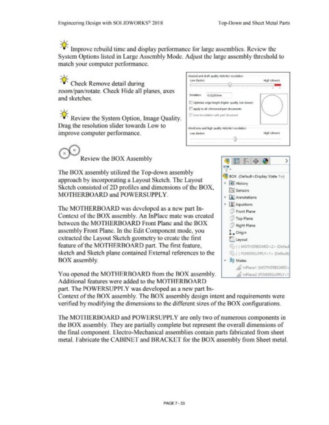
-;Q~ Improve rebuild time and display performance for large assemblies. Review the
System Options listed in Large Assembly Mode. Adjust the large assembly threshold to
match your computer performance.
, ,/ Shaded and draft quality HLR/HLV resolution
Low (faster} High (slower}
-;Q~ Check Remove detail during ,------------------------10~-------------------------~--
' ' . ' .
zoom/pan/rotate. Check Hide all planes, axes
Deviation: 03 1250mm
and sketches.
IC] Optimize edge length (higher quality, but slower)
, ,/ D Apply to all referenced part documents
0 save tessellation with part document
-;Q~ Review the System Option, Image Quality.
Drag the resolution slider towards Low to
Wireframe and high quality HLR/HLV resolution
improve computer performance. Low (faster) High (slower)
0
,,~~ ( ) ' ' ' '
,: () ~~
"".rr-· Review the BOX Assembly
~ ~ lt8 -$ >
v·
The BOX assembly utilized the Top-down assembly
~ BOX (Default<Display State-1>)
approach by incorporating a Layout Sketch. The Layout
~ ~] History
Sketch consisted of 2D profiles and dimensions of the BOX,
[al Sensors
MOTHERBOARD and POWERSUPPL Y.
~ IA] Annotations
~ ~ Equations
The MOTHERBOARD was developed as a new part In-
dJ Front Plane
Context of the BOX assembly. An InPlace mate was created
dJ Top Plane
between the MOTHERBOARD Front Plane and the BOX
dJ Right Plane
assembly Front Plane. In the Edit Component mode, you L Origin
extracted the Layout Sketch geometry to create the first L Layout
feature of the MOTHERBOARD part. The first feature, '.;) (-) MOTHERBOARD<2> (Defaul
sketch and Sketch plane contained External references to the '-.L~ (-) POWERSUPPLY<1> (Default)
BOX assembly. • ®@ Mates
6 lnPlace1 (MOTHERBOARD<
You opened the MOTHERBOARD from the BOX assembly. ,4 lnPlace2 (POWERSUPPL Y < 1
Additional features were added to the MOTHERBOARD
part. The POWERSUPPL Y was developed as a new part In-
Context of the BOX assembly. The BOX assembly design intent and requirements were
verified by modifying the dimensions to the different sizes of the BOX configurations.
The MOTHERBOARD and POWERSUPPL Y are only two of numerous components in
the BOX assembly. They are partially complete but represent the overall dimensions of
the final component. Electro-Mechanical assemblies contain parts fabricated from sheet
metal. Fabricate the CABINET and BRACKET for the BOX assembly from Sheet metal.
PAGE 7 -33