Page 604 - Subyek Computer Aided Design - [David Planchard] Engineering Design with SOLIDWORKS
P. 604

Top-Down and Sheet Metal Parts                                                                                                                             Engineering Design with SOLIDWORKS® 2018


                                                Add additional sheet metal Edge Flange and Hem features. Add dies, louvers, and cuts to


                                                complete the CABINET.


                                                Utilize configurations to create the 3D formed state for the BOX assembly and the


                                                2D flat state for the CABINET drawing.


                                                   Activity: CABINET-Insert Component


                                                Insert the CABINET Component.


                                                195) If needed, open the BOX assembly.


                                                                                                                                                                                                                                                                                Insert               Mate             (ompone
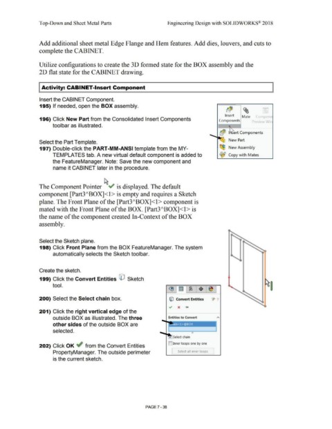
                                                196) Click New Part from the Consolidated Insert Components                                                                                                                                                              Components                              p eview Win


                                                                toolbar as illustrated.


                                                                                                                                                                                                                                                                          'a~  I  ert Components

                                                                                                                                                                                                                                                              ~
                                                                                                                                                                                                                                                                                     New Part
                                                Select the Part Template.


                                                197) Double-click the PART-MM-ANSI template from the MY-                                                                                                                                                                  ~ New Assembly


                                                                TEMPLATES tab. A new virtual default component is added to                                                                                                                                                ~ Copy with  Mates


                                                                the FeatureManager. Note: Save the new component and


                                                                 name it CABINET later in the procedure.


                                                The Component Pointer ~"  is displayed. The default


                                                component [Part3/\BOX]<l> is empty and requires a Sketch


                                                plane. The Front Plane of the [Part3/\BOX]<l > component is


                                                mated with the Front Plane of the BOX. [Part3/\BOX]<l > is


                                                the name of the component created In-Context of the BOX


                                                assembly.


                                                Select the Sketch plane.


                                                198) Click Front Plane from the BOX FeatureManager. The system


                                                                 automatically selects the Sketch toolbar.


                                                Create the sketch.


                                                199) Click the Convert Entities CO  Sketch


                                                                tool.


                                                200) Select the Select chain box.                                                                                                                            © Convert Entities                                 ·1>  ·1


                                                201) Click the right vertical edge of the


                                                                 outside BOX as illustrated. The three                                                                                                      Entities to Convert                                       "


                                                                 other sides of the outside BOX are


                                                                 selected.                                                                                                                                                              e


                                                                                                                                                                                                                  Select chain


                                                                                                                                                                                                            []Inner loops one by one
                                                202) Click OK ~ from the Convert Entities


                                                                 PropertyManager. The outside perimeter                                                                                                         [      Select all  inner loops  ]


                                                                 is the current sketch.


                                                                                                                                                                                PAGE? - 38
   599   600   601   602   603   604   605   606   607   608   609