
Page 585 - Subyek Computer Aided Design - [David Planchard] Engineering Design with SOLIDWORKS
P. 585
Engineering Design with SOLIDWORKS® 2018 Top-Down and Sheet Metal Parts
81) Click the lower right horizontal dimension
20 in the Graphics window. The dimension
name is displayed in the Value/Equation 20
column. Note: Your dimension name may be
different. A green check mark indicates the
value can be calculated.
I
'
82) Press the Tab key. The Evaluates to column
displays 20. ....
,
- ..... ~
83) Enter Gap from the Cabinet wall for
comment. The first Global Variable Gap is
defined. Next define equations to equate the other variables to Gap.
84) Click inside the first cell below Equations-Top Level.
85) Click the lower right vertical dimension 20 in the Graphics window.
86) Slide the mouse pointer to the right of Global Variables to display Gap (20mm).
87) Click Gap {20mm).
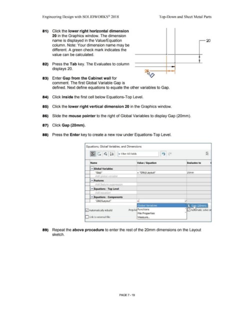
88) Press the Enter key to create a new row under Equations-Top Level.
Equations, Global Variables, and Dimensions
[ X. 11 ~ 11 ~ 11 ~ l I ~jw_Fi_lte_r _AI_I F_ie_lds ____ ~l I ~ I p
Name Value I Equation Evaluates to
- Global Variables
"Ga O = "D9@La out" 20mm
Add lobal variable
- Features
Add eature sup ression
- Equations - Top Level
Add equation
1.----,
- Equations - Components
"D8@La out"
12] Automatically rebuild Angula Functions > lvl A matic solve o
>
File Properties
D Link to external file: Measure ...
89) Repeat the above procedure to enter the rest of the 20mm dimensions on the Layout
sketch.
PAGE 7 - 19