
Page 580 - Subyek Computer Aided Design - [David Planchard] Engineering Design with SOLIDWORKS
P. 580
Top-Down and Sheet Metal Parts Engineering Design with SOLIDWORKS® 2018
The BOX assembly contains the following key components:
• POWERSUPPLY.
• MOTHERBOARD.
The minimum physical spatial gap between the MOTHERBOARD and the
POWERSUPPL Y is 25mm. The minimum physical spatial gap between the
MOTHERBOARD, POWERSUPPL Y and the internal sheet metal BOX wall is 20mm.
After numerous discussions with the electrical engineer, you standardize on a
POWERSUPPLY size: 150mm x 75mm x 50mm. You know the overall dimensions for
the BOX, POWERSUPPLY and MOTHERBOARD. You also know the dimensional
relationship between these components.
Now you must build these parameters into the design intent of the sketch. There is no
symmetry between the major components. Locate the sketch with respect to the BOX
assembly Origin.
I Activity: Box Assembly and Sketch Layout
Create the BOX assembly.
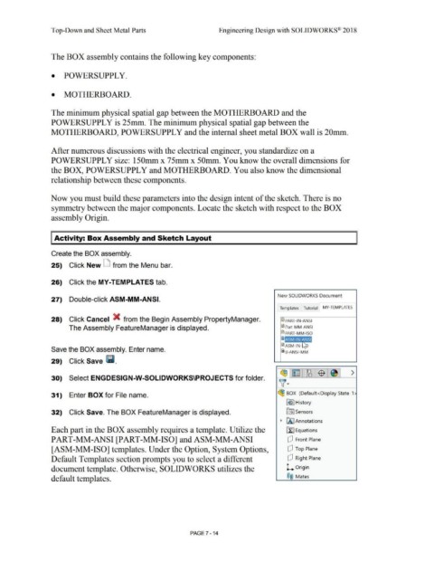
25) Click New D from the Menu bar.
26) Click the MY-TEMPLATES tab.
New SOLIDWORKS Document
27) Double-click ASM-MM-ANSI.
Templates Tutorial MY-TEM PLATES
28) Click Cancel X from the Begin Assembly PropertyManager. ~ PART-IN-ANSI
The Assembly FeatureManager is displayed. ~ Part-M M-ANSI
@:l PART-MM-ISO
i~i,11,0!,1
!ID ASM-IN-
Save the BOX assembly. Enter name.
i s-ANSI-MM
29) Click Save lli.
r:!11 1~ : ~ J$ J >
30) Select ENGDESIGN-W-SOLIDWORKS\PROJECTS for folder.
~ ·
31) Enter BOX for File name. (!B BOX (Default<Display State-1
f€> I History
32) Click Save. The BOX FeatureManager is displayed. [:ii Sensors
~ f'.A. I Annotations
Each part in the BOX assembly requires a template. Utilize the [fJ Equations
PART-MM-ANSI [PART-MM-ISO] andASM-MM-ANSI dJ Front Plane
[ASM-MM-ISO] templates. Under the Option, System Options, dJ Top Plane
Default Templates section prompts you to select a different dJ Right Plane
document template. Otherwise, SOLIDWORKS utilizes the L Origin
default templates. ®@ Mates
PAGE 7 - 14