
Page 579 - Subyek Computer Aided Design - [David Planchard] Engineering Design with SOLIDWORKS
P. 579
Engineering Design with SOLIDWORKS® 2018 Top-Down and Sheet Metal Parts
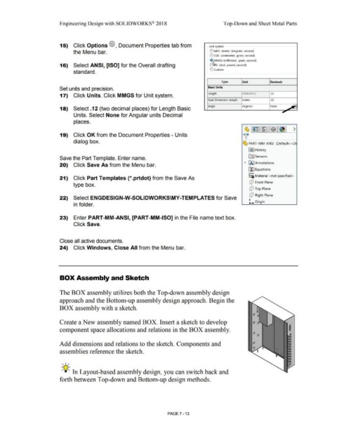
15) Click Options @, Document Properties tab from Unit system
the Menu bar. e) MKS (meter, kilogram, second)
e) CGS (centimeter, gram, second)
@ MMGS (millimeter, gram, second)
16) Select ANSI, [ISO] for the Overall drafting ~ S (inch, pound, second)
e) custom
standard.
Type Unit Decimals
Set units and precision. Basic Units
17) Click Units. Click MMGS for Unit system. Length millimeters .12
Dual Dimension Length inches .12
Angle degrees None
18) Select .12 (two decimal places) for Length Basic ~
Units. Select None for Angular units Decimal
places.
~ I ~ 1=r12 ~ I I >
19) Click OK from the Document Properties - Units ~
dialog box. ~ PART-MM-ANSI (Default<<D
lli> J History
Save the Part Template. Enter name. [0:J Sensors
20) Click Save As from the Menu bar. • IA] Annotations
ll::J Equations
o-
21) Click Part Templates (*.prtdot) from the Save As :=o Material <not specified>
dJ Front Plane
type box.
dJ Top Plane
dJ Right Plane
22) Select ENGDESIGN-W-SOLIDWORKS\MY-TEMPLATES for Save
L Origin
in folder.
23) Enter PART-MM-ANSI, [PART-MM-ISO] in the File name text box.
Click Save.
Close all active documents.
24) Click Windows, Close All from the Menu bar.
BOX Assembly and Sketch
The BOX assembly utilizes both the Top-down assembly design
approach and the Bottom-up assembly design approach. Begin the
BOX assembly with a sketch.
Create a New assembly named BOX. Insert a sketch to develop
component space allocations and relations in the BOX assembly. I
Add dimensions and relations to the sketch_ Components and
assemblies reference the sketch.
, ,/
-;Q~ In Layout-based assembly design, you can switch back and
forth between Top-down and Bottom-up design methods.
PAGE 7 - 13