
Page 576 - Subyek Computer Aided Design - [David Planchard] Engineering Design with SOLIDWORKS
P. 576
Top-Down and Sheet Metal Parts Engineering Design with SOLIDWORKS® 2018
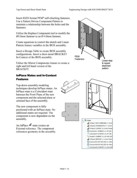
Insert IGES format PEM® self-clinching fasteners.
Use a Pattern Driven Component Pattern to
maintain a relationship between the holes and the
fasteners.
Utilize the Replace Component tool to modify the
05.0mm fastener to an 0 4.0mm fastener.
Create equations to control the sketch and Linear
Pattern feature variables in the BOX assembly.
Insert a Design Table to create BOX assembly
configurations. Insert a sheet metal BRACKET
In-Context of the BOX assembly. PEM
Fasteners
Linear step
Utilize the Mirror Components feature to create a & repeat
right and left hand version of the sketched
pattern
BRACKET.
lnPlace Mates and In-Context
Features
Top-down assembly modeling I
techniques develop InPlace mates. An ,,
InPlace mate is a Coincident mate ,,
between the Front Plane of the new
component and the selected plane or ,,
selected face of the assembly.
The new component is fully 0 0
positioned with an InPlace mate. No
,
additional mates are required. The
component is now dependent on the 0 0
assembly.
~ ®@ Mates
" lnPlace1 (MOTHERBOARD<1 >,Fron
An InPlace ~ mate creates an ~ lnPlace2 (POWERSUPPLY<1>,Front
External reference. The component ~ lnPlace3 (CABINET <2>,Front Plane)
references geometry in the assembly. @ concentric1 (CABINET <2>,FH-M4-:
/\ Coincident1 (CABINET <2>,FH-M4-:
~ Parallel1 (CABINET <2>,FH-M4-25Z
JS lnPlace4 (BRACKET <1 >,Front Plane:
@ concentric3 (FH-M4-25ZI <5>,Mirrc
@ concentric4 (FH-M4-25Z1 <4>,Mirrc
/\ Coincident4 (CABINET <2>,MirrorBF
PAGE 7 - 10