Page 581 - Subyek Computer Aided Design - [David Planchard] Engineering Design with SOLIDWORKS
P. 581

Engineering Design with SOLIDWORKS® 2018                                                                                                                                                          Top-Down and Sheet Metal Parts


                                                                        Set System Options.


                                                                        33)  Click Options  © , Default Templates from                                                                                                                System Op1io1,s  Ooc.umem P,opetties


                                                                                                                                                                                                                                     General                                                             Open last used document(s) at startup:   N~           v
                                                                                        the Menu bar.                                                                                                                                Drawings

                                                                                                                                                                                                                                      Display Style                                                      121 input dimen~on val~
                                                                                                                                                                                                                                      Area t-&atchlfil                                                   Osing1e commc,nd PE'f pc(t
                                                                                                                                                                                                                                      Periormal'l(e                                                      E2l US< shaded t,cc >.Jhllgh\;119
                                                                                                                                                                                                                                     COi ...                                                             0 Show thumbnail oraphics in Windows Explorer
                                                                        34)  Click the Prompt user to select document                                                                                                                Sletten                                                             0Use sys1tfl'l ~ 1:.lJrator tor di1nensioos
                                                                                                                                                                                                                                       Rel11tions!Snaps
                                                                                                                                                                                                                                     Dwsplay
                                                                                        template button. Click OK.                                                                                                                   Seloolon                                                               U'M' r nqtn,h J,.n,,u~qP fillilut"' ~,d l'ii. n,.s'fl4!',,


                                                                                                                                                                                                                                                                                                         0 Ena~ Co.,l'i,m.;itioo comer
                                                                                                                                                                                                                                     External References                                                 0 Auto show PropertyMaMger
                                                                                                                                                                                                                                     Oefat;IJ T 'llfWlt'llPS                                             0 Al.1lo--sil.t Prop@rtyM~MgE!r ~ p .. n@ls ..... e ,q>lit
                                                                        The 2D sketch contains the 2D relationships                                                                                                                  Fi<Loc•U                                                            D Au'lom,1tic.1lly edrl m.ioo _.he, nicording
                                                                                                                                                                                                                                     FeotureMon.,g,er


                                                                       between all major components in the BOX


                                                                        assembly.


                                                                        Select the Sketch plane for the sketch.


                                                                        35)  Right-click Front Plane from the FeatureManager.


                                                                        Sketch the profile of the BOX.


                                                                        36)  Click Sketch L  from the Context toolbar. The Sketch


                                                                                        toolbar is displayed. Click Corner Rectangle D  from


                                                                                        the Sketch toolbar.


                                                                                                                                                                                                                                                                            ___..
                                                                        37)  Click the Origin. Sketch a rectangle as illustrated.


                                                                                        The first point is coincident with the Origin.


                                                                                                                                                                                                                                                                   Origin


                                                                       Add dimensions.


                                                                        38)  Click Smart Dimension  (' from the Sketch toolbar.


                                                                        39)  Click the left vertical line. Click a position to the left of the profile.


                                                                                        Enter 400mm.


                                                                        40)  Click the bottom horizontal line. Click a position below the


                                                                                        profile. Enter 300mm.


                                                                        Fit the model to the Graphics window.


                                                                        41)  Press the f key.


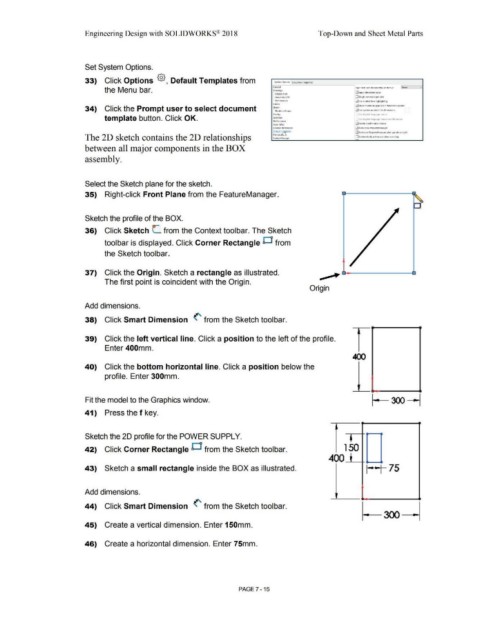
                                                                        Sketch the 20 profile for the POWER SUPPLY.


                                                                       42)  Click Corner Rectangle O  from the Sketch toolbar.                                                                                                                                                                  1  50


                                                                                                                                                                                                                                                                                   400


                                                                        43)  Sketch a small rectangle inside the BOX as illustrated.                                                                                                                                                                              I • ~ I            75


                                                                       Add dimensions.


                                                                       44)  Click Smart Dimension  (' from the Sketch toolbar.


                                                                        45)  Create a vertical dimension. Enter 150mm.


                                                                        46)  Create a horizontal dimension. Enter 75mm.


                                                                                                                                                                                                        PAGE 7-15
   576   577   578   579   580   581   582   583   584   585   586