
Page 582 - Subyek Computer Aided Design - [David Planchard] Engineering Design with SOLIDWORKS
P. 582
Top-Down and Sheet Metal Parts Engineering Design with SOLIDWORKS® 2018
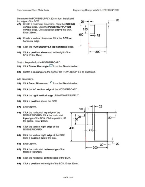
Dimension the POWERSUPPL Y 20mm from the left and
-20
top edges of the BOX. 20 ~ t
47) Create a horizontal dimension. Click the BOX left
vertical edge. Click the POWERSUPPLY left
vertical edge. Click a position above the BOX. 1 50
Enter 20mm.
400 ,--, 75
48) Create a vertical dimension. Click the BOX top
horizontal edge.
49) Click the POWERSUPPL Y top horizontal edge.
50) Click a position above and to the right of the
BOX. Enter 20mm.
Sketch the profile for the MOTHERBOARD.
51) Click Corner Rectangle D from the Sketch tool bar.
52) Sketch a rectangle to the right of the POWERSUPPL Y as illustrated.
Add dimensions.
53) Click Smart Dimension (' from the Sketch toolbar.
54) Click the left vertical edge of the MOTHERBOARD.
55) Click the right vertical edge of the POWERSUPPL Y.
56) Click a position above the BOX.
57) Enter 25mm. 25
20]
58) Click the horizontal top edge of the " t
MOTHERBOARD. Click the horizontal
20
top edge of the BOX. Click a position off 20
1 50
the profile. Enter 20mm.
59) Click the vertical right edge of the 400
MOTHERBOARD. 75
60) Click the vertical right edge of the BOX.
Click a position below the Box.
l
61) Enter 20mm. 20
20
300 -
62) Click the horizontal bottom edge of the
MOTHERBOARD.
63) Click the horizontal bottom edge of the BOX.
64) Click a position to the right of the BOX. Enter 20mm.
PAGE 7 - 16