Page 583 - Subyek Computer Aided Design - [David Planchard] Engineering Design with SOLIDWORKS
P. 583

Engineering Design with SOLIDWORKS® 2018                                                                                                                                                          Top-Down and Sheet Metal Parts


                                                                          , ,/


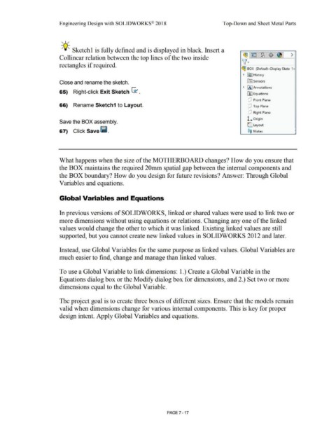
                                                                          -;Q~ Sketchl is fully defined and is displayed in black. Insert a


                                                                                                                                                                                                                                                                                                   ~1~ 1~1$ 1~1 >
                                                                        Collinear relation between the top lines of the two inside


                                                                        rectangles if required.                                                                                                                                                                                                   v·

                                                                                                                                                                                                                                                                                                 ~ BOX  (Default<Display State-1 >


                                                                                                                                                                                                                                                                                                   •  ~I History


                                                                        Close and rename the sketch.                                                                                                                                                                                                    ~      Sensors


                                                                                                                                                                                                                                                                                                  • IA I Annotations
                                                                        65)  Right-click Exit Sketch G1 .


                                                                                                                                                                                                                                                                                                        Lf::I Equations


                                                                                                                                                                                                                                                                                                         dJ  Front Plane

                                                                        66)  Rename Sketch1 to Layout.                                                                                                                                                                                                   dJ  Top Plane


                                                                                                                                                                                                                                                                                                         dJ  Right Plane


                                                                                                                                                                                                                                                                                                        l. Origin
                                                                        Save the BOX assembly.

                                                                                                                                                                                                                                                                                                        C Layout

                                                                        67)  Click Save (ii.                                                                                                                                                                                                            ®@  Mates                                               '


                                                                        What happens when the size of the MOTHERBOARD changes? How do you ensure that


                                                                        the BOX maintains the required 20mm spatial gap between the internal components and


                                                                        the BOX boundary? How do you design for future revisions? Answer: Through Global


                                                                        Variables and equations.


                                                                        Global Variables and Equations


                                                                        In previous versions of SOLIDWORKS, linked or shared values were used to link two or


                                                                        more dimensions without using equations or relations. Changing any one of the linked


                                                                        values would change the other to which it was linked. Existing linked values are still


                                                                        supported, but you cannot create new linked values in SOLIDWORKS 2012 and later.


                                                                        Instead, use Global Variables for the same purpose as linked values. Global Variables are


                                                                        much easier to find, change and manage than linked values.


                                                                        To use a Global Variable to link dimensions: 1.) Create a Global Variable in the


                                                                        Equations dialog box or the Modify dialog box for dimensions, and 2.) Set two or more


                                                                        dimensions equal to the Global Variable.


                                                                        The project goal is to create three boxes of different sizes. Ensure that the models remain


                                                                        valid when dimensions change for various internal components. This is key for proper


                                                                        design intent. Apply Global Variables and equations.


                                                                                                                                                                                                        PAGE 7 - 17
   578   579   580   581   582   583   584   585   586   587   588