
Page 575 - Subyek Computer Aided Design - [David Planchard] Engineering Design with SOLIDWORKS
P. 575
Engineering Design with SOLIDWORKS® 2018 Top-Down and Sheet Metal Parts
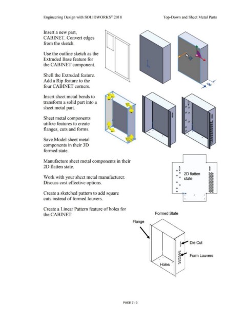
Insert a new part,
CABINET. Convert edges
from the sketch.
Use the outline sketch as the
Extruded Base feature for
the CABINET component.
Shell the Extruded feature.
Add a Rip feature to the
four CABINET comers.
Insert sheet metal bends to
transform a solid part into a
sheet metal part.
Sheet metal components
utilize features to create
flanges, cuts and forms.
Save Model sheet metal
components in their 3D
formed state.
Manufacture sheet metal components in their
2D flatten state.
0 ~
° 20 flatten
Work with your sheet metal manufacturer. 0 O state
Discuss cost effective options. 0
0
0
Create a sketched pattern to add square 0
• • •
cuts instead of formed louvers. • •
Create a Linear Pattern feature of holes for
the CABINET. Formed State
Flange
Die Cut
. ,
- Form Louvers
Holes ·
PAGE 7 - 9