
Page 613 - Subyek Computer Aided Design - [David Planchard] Engineering Design with SOLIDWORKS
P. 613
Engineering Design with SOLIDWORKS® 2018 Top-Down and Sheet Metal Parts
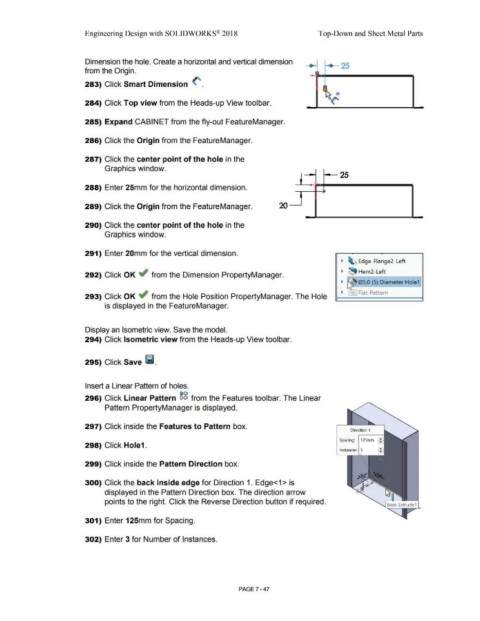
Dimension the hole. Create a horizontal and vertical dimension
- - 25
from the Origin. ,
283) Click Smart Dimension <".
f '\. *
--~('
284) Click Top view from the Heads-up View toolbar.
285) Expand CABINET from the fly-out FeatureManager.
286) Click the Origin from the FeatureManager.
287) Click the center point of the hole in the
Graphics window.
~ 25
288) Enter 25mm for the horizontal dimension. i
:,
289) Click the Origin from the FeatureManager. 20 "
.
290) Click the center point of the hole in the
Graphics window.
291) Enter 20mm for the vertical dimension.
~ ~ Edge-Flange2-Left
~ ~ Hem2-Left
292) Click OK ~ from the Dimension PropertyManager.
~ 05.0 (5) Diameter Hole1
~ 1 ~ Flat-Pattern
293) Click OK ~ from the Hole Position PropertyManager. The Hole
is displayed in the FeatureManager.
Display an Isometric view. Save the model.
294) Click Isometric view from the Heads-up View toolbar.
295) Click Save l'i.
Insert a Linear Pattern of holes.
296) Click Linear Pattern ~g from the Features toolbar. The Linear
Pattern PropertyManager is displayed.
297) Click inside the Features to Pattern box.
Direction 1
125mrn I: I
Spacing:
298) Click Hole1.
Instances: 3
299) Click inside the Pattern Direction box.
300) Click the back inside edge for Direction 1. Edge<1 > is
displayed in the Pattern Direction box. The direction arrow
points to the right. Click the Reverse Direction button if required.
'
301) Enter 125mm for Spacing.
302) Enter 3 for Number of Instances.
PAGE 7 - 47