
Page 618 - Subyek Computer Aided Design - [David Planchard] Engineering Design with SOLIDWORKS
P. 618
Top-Down and Sheet Metal Parts Engineering Design with SOLIDWORKS® 2018
, 1 /
;Q~ With thin sheet metal parts, select the dimension references with care. Use the Zoom
and Rotate commands to view the correct edge. Use reference planes or the Origin to
create dimensions. The Origin and planes do not change during the flat and formed states.
, 1 /
;Q~ Save time with the Modify Sketch tool. Utilize the left
and right mouse point positioned on the large black dots. 0
The left button Pans and the right button Rotates. The
center dot reorients the Origin of the sketch and Mirrors the
' r I'- ~ 1L
L
•
"'~
~
~
'I:
sketch about y, x or both.
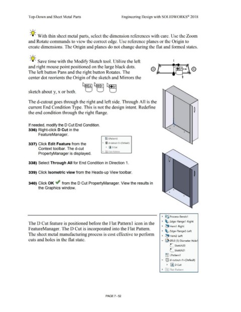
The d-cutout goes through the right and left side. Through All is the
current End Condition Type. This is not the design intent. Redefine
the end condition through the right flange.
If needed, modify the D Cut End Condition.
336) Right-click D Cut in the
FeatureManager.
~g LPatternl
337) Click Edit Feature from the "' ®I d-cutout<l >(Default)
Context toolbar. The d-cut • ii D Cut
• F-1 Flat-Pattern
PropertyManager is displayed.
338) Select Through All for End Condition in Direction 1.
339) Click Isometric view from the Heads-up View toolbar.
340) Click OK ~ from the D Cut PropertyManager. View the results in
the Graphics window.
• §~ Process- Bends1
• ~ Edge-Flange1 -Right
The D Cut feature is positioned before the Flat Patteml icon in the
• ~ Hem1 -Right
F eatureManager. The D Cut is incorporated into the Flat Pattern.
• ~ Edge-Flange2- Left
The sheet metal manufacturing process is cost effective to perform
• ~ Hem2- Left
cuts and holes in the flat state. .,... ~ 05.0 (5) Diameter Hole1
.-
.- Sketch20
L
L Sketch21
~g LPattern1
..... ®J d-cutout<1 >(Default)
• ~ D Cut
• f~I Flat-Pattern
PAGE?-52