
Page 617 - Subyek Computer Aided Design - [David Planchard] Engineering Design with SOLIDWORKS
P. 617
Engineering Design with SOLIDWORKS® 2018 Top-Down and Sheet Metal Parts
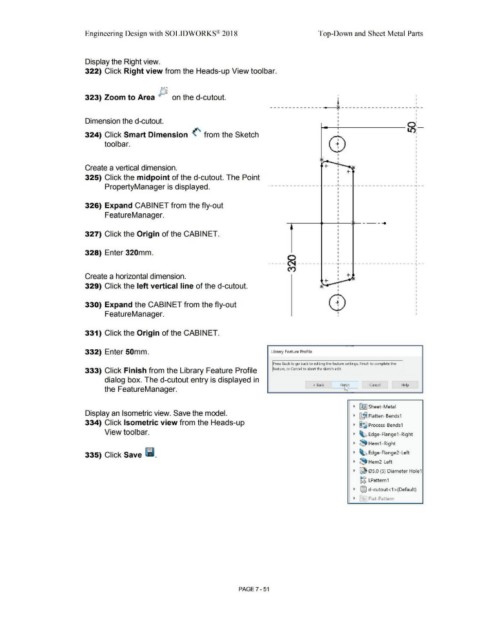
Display the Right view.
322) Click Right view from the Heads-up View toolbar.
323) Zoom to Area P, on the d-cutout. • I I
I
---------------4 -------------------_ :_ -
I
I
i------,,--------0:-
Dimension the d-cutout. I
324) Click Smart Dimension (' from the Sketch I l/),
tool bar.
I
I
I
Create a vertical dimension. I '
I +-
I
325) Click the midpoint of the d-cutout. The Point
I
PropertyManager is displayed. . - - - - - - - - - - - - - . - - - _ ,_ - - - - - - - - - - - - - - - - - - - -i - -
I
326) Expand CABINET from the fly-out
FeatureManager. I
I __ ...
•
327) Click the Origin of the CABINET.
328) Enter 320mm.
0
----- ~ ------ ----,--------------------,--
I
cry I I
I I
Create a horizontal dimension. I +- Jv
I
+-
329) Click the left vertical line of the d-cutout. ~-- I
I
'
330) Expand the CABINET from the fly-out
FeatureManager.
331) Click the Origin of the CABINET.
332) Enter 50mm. Library Feature Profile
Press Back to go back to editing the feature settings, Finish to complete the
333) Click Finish from the Library Feature Profile eature, or Cancel to abort the sketch edit.
dialog box. The d-cutout entry is displayed in
< Back Fiq'.$,,____, Cancel Help
the FeatureManager. -
• ~ Sheet-Metal
Display an Isometric view. Save the model.
• ~~ Flatten-Bends1
334) Click Isometric view from the Heads-up • ~~ Process-Bends1
View toolbar. • ~ Edge-Flange1-Right
~ ~ Hem1 -Right
335) Click Save lil. • ~ Edge-Flange2-Left
• ~ Hem2-Left
• ~ 05.0 (5) Diameter Hole1
~~ LPattern1
~ @l d-cutout< 1 >(Default)
• ~' Flat-Pattern
PAGE 7 - 51