
Page 627 - Subyek Computer Aided Design - [David Planchard] Engineering Design with SOLIDWORKS
P. 627
Engineering Design with SOLIDWORKS® 2018 Top-Down and Sheet Metal Parts
413) Drag the sw-b212 feature to the inside left face of the CABINET. The
sw-b212 PropertyManager is displayed.
414) Click the Edit Sketch button. DO NOT SELECT THE FINISH BUTTON
AT THIS TIME.
Selected Entitles ~
+
Add a Midpoint relation between the center point of the sw- linelO
Pointl@Sketch-Random
b212 feature and the first random sketch point.
415) Click the vertical centerline of sw-b212. I
+-
Existi,,g Relations ~
416) Hold the Ctrl key down. j,_ Midpoint28
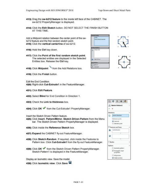
417) Click the Point of the first random sketch point.
The selected entities are displayed in the Selected
0 Fully Defined
Entities box. Release the Ctrl key.
AddRelmoM ~
~ Midpoint
Coincident
418) Click Midpoint ' from the Add Relations box. +
419) Click the Finish button.
Edit the End Condition.
420) Right-click Cut-Extrude1 in the FeatureManager.
421) Click Edit Feature.
422) Select Blind for End Condition in Direction 1.
423) Check the Link to thickness box.
•
~l!i.;, Sketch-Pattern! '/
424) Click OK ~ from the Cut-Extrude1 PropertyManager. ~ x
Selections
Insert the Sketch Driven Pattern feature. 11.: I Sketch-Random ]
425) Click Insert, Pattern/Mirror, Sketch Driven Pattern from the Menu Reference point:
bar. The Sketch Driven Pattern PropertyManager is displayed. @ centroid
(0 Selected point
426) Click inside the Reference Sketch box. 0 Features and Faces
&i I Cut-Extrudel
427) Expand the CABINET fly-out FeatureManager. 0
428) Click Sketch-Random. If required, click inside the Features to
Pattern box. Click Cut-Extrude1 from the fly-out FeatureManager. ID Bodies v
Options
429) Click OK ~ from the Sketch Driven Pattern PropertyManager. D Geometry pattern
0 Propagate visual
Sketch-Pattern 1 is displayed in the FeatureManager. prope_rties
(0 Full preview
@ Partial preview
Display an Isometric view. Save the model.
430) Click Isometric view. Click Save lill.
PAGE 7 - 61