
Page 153 - Enhanced Oil Recovery in Shale and Tight Reservoirs
P. 153
Gas flooding compared with huff-n-puff gas injection 137
of higher pressure gradient, but it lowers late-time rate; higher mechanical
dispersion slightly decreases the ultimate recovery. These results are
expected. The main issue is the technical difficulties and economic return
to complete the horizontal well so that two sets of alternate fractures can
be used for injection and production. But the designs of such a downhole
tool are available (Sharma et al., 2013; MacPhail et al., 2014).
6.3 Gas flooding versus huff-n-puff gas injection
Huff-n-puff gas injection has been studied by experiments and simu-
lation work, and it has been found that it is an effective EOR method in
shale and tight reservoirs. However, gas flooding is much more used method
in conventional reservoirs. A very important question arises: which method
should be a preferred method?
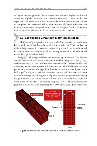
Sheng (2015d) compared these two methods by simulation. The dimen-
sions of the base model are the same as that used by Sheng and Chen (2014),
as shown in Fig. 6.5. Two half-fractures are included in the base model. For
a flooding mode, one injector is located in the left half-fracture and one
producer is located in the right half-fracture, as shown in the figure. For a
huff-n-puff mode, two wells are located in the two half-fractures, and these
two wells are injectors during the huff period and become producers during
the puff period. Such setup makes the flow area and number of wells the
same in the two modes. The fracture length is 1000 ft. The initial reservoir
pressure is 6425 psi. The permeability is 100 nanoDarcy. The porosity is
Figure 6.5 Dimensions and well locations in the base reservoir model.