
Page 148 - Enhancing CAD Drawings with Photoshop
P. 148
4386.book Page 131 Monday, November 15, 2004 3:27 PM
ENTOURAGE IN AUTODESK VIZ 131
WARNING Anyone well acquainted with computer graphics can spot specific pieces of entourage
that seem to get used over and over again by beginners. Chances are, any free entourage you can find
on the Web has been used countless times by others looking for an easy way to dress up their ren-
derings. Your best bet is to either make or buy quality entourage. Your renderings will appear more
professional.
Check out these websites for more information on buying professional quality entourage:
www.archvision.com
www.marlinstudios.com
www.imagecels.com
Entourage in Autodesk VIZ
Using entourage in a 3D program is simple in concept, but often difficult in practice. We will look at
the procedure for setting up entourage in Autodesk VIZ 2005. The steps are similar in other versions
of VIZ and 3ds max. The concepts you learn here will apply in other 3D programs, although the steps
may be different, depending on the features of the software.
The main idea is that you take the photographic entourage you create in Photoshop and use it in
a material that you design in VIZ. This material defines the surface qualities of a 3D object and uses
both the color pixels and alpha channel of the entourage file. You map this material to the surface of
plane geometry to create the illusion of a 2D cutout in a 3D scene.
Creating Entourage Geometry
The first order of business is to make a flat object onto which you’ll later map a material. Although any
flat geometry will do, an object that has the correct orientation and pivot point location for ease of
manipulating the object in a 3D scene is better. Follow these steps:
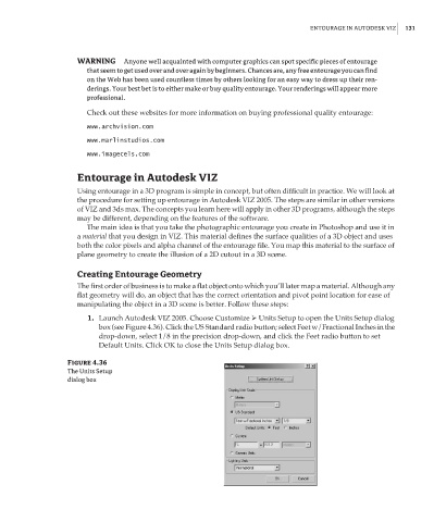
1. Launch Autodesk VIZ 2005. Choose Customize Units Setup to open the Units Setup dialog
box (see Figure 4.36). Click the US Standard radio button; select Feet w/Fractional Inches in the
drop-down, select 1/8 in the precision drop-down, and click the Feet radio button to set
Default Units. Click OK to close the Units Setup dialog box.
Figure 4.36
The Units Setup
dialog box