
Page 176 - Entrophy Analysis in Thermal Engineering Systems
P. 176
Exergy 171
with the minimum entropy generation if all Q j and Q k terms in Eq. (11.5)
are fixed.
Now, the thermal exergy is defined as
T 0
th
Ψ ¼ 1 T i Q i (11.8)
It represents the maximum theoretical work extractable from a given quan-
tity of heat Q i in a closed cycle operating between two thermal reservoirs
maintained at T i and T 0 . Given the definition of the thermal exergy, Eq.
(11.5) may be expressed as
p
n
X X
W net ¼ Ψ th (11.9)
th
j Ψ Ψ de
k
j¼1 k¼p +1
where Ψ de ¼T 0 Φ denotes exergy destruction. If all Q j and Q k are assumed to
be constant, Ψ j and Ψ k will also be constant. Then, maximization of work
th
th
output would be identical to minimization of exergy destruction or of
entropy generation.
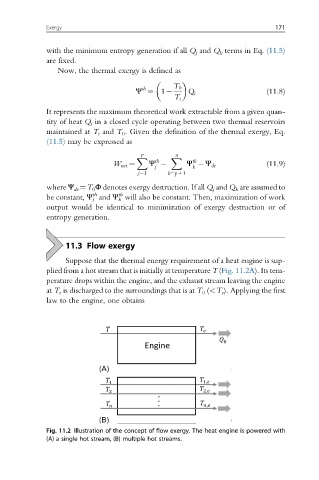
11.3 Flow exergy
Suppose that the thermal energy requirement of a heat engine is sup-
plied from a hot stream that is initially at temperature T (Fig. 11.2A). Its tem-
perature drops within the engine, and the exhaust stream leaving the engine
at T e is discharged to the surroundings that is at T 0 (<T e ). Applying the first
law to the engine, one obtains
Fig. 11.2 Illustration of the concept of flow exergy. The heat engine is powered with
(A) a single hot stream, (B) multiple hot streams.