
Page 237 - Essentials of physical chemistry
P. 237
Basic Spectroscopy 199
but the x-rays tend to be generated in a region of space near the sample stage. Some x-rays can be
collimated using a slit or hole that faces a crystal-lattice grid such as a plate of LiF to cause
diffraction of the x-rays into a sort of ‘‘x-ray rainbow.’’ The dispersed spectrum can then be detected
using photographic film blackening or with modern electronic detectors. One possible detector is a
small block of pure Si with a core region of Li immersed in liquid N 2 and under a voltage potential.
When an x-ray hits the Li in the detector, a cascade of ionized electrons results in a ‘‘pulse-count.’’
The Li core is the active electrode and the Si provides a nonconducting shell around the Li. The low
temperature is to provide a low ‘‘dark current thermal ionization’’ until an energetic x-ray hits the
detector and causes a big signal due to ionized electrons. The detector can be moved along a
wavelength track or a number of the detectors can be used in fixed positions corresponding to
different wavelengths. Students have asked why the device used for the spectrum in Figure 9.9
required liquid N 2 . The answer is that the detector needs to be at a low temperature (778K) to reduce
spurious thermal signals. A very good description of x-ray detection is given in Ref. [7].
X-RAY DIFFRACTION
At this point, we need to explain an important aspect of almost any form of spectroscopy, which is
the need to disperse a spectral rainbow into individual components. For optical spectra in the visible
or even the infrared range, one can employ a wedge (prism) of a transparent material such as glass,
quartz, or even potassium bromide. Different refractive indices for different colors will fan out
(disperse) the rainbow of a beam of light. There is another method of dispersing light. Light can be
‘‘diffracted’’ from a grid of grooved lines on a reflecting surface (a grating) so that light is reflected
differently from the crests and troughs of the grooves. Then the electric fields of the light cancel out
except at certain angles of reflection based on the basic law of diffraction that we illustrate in
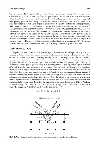
Figure 9.6. This phenomena can also be used to diffract light from regular crystal lattice features if
we have a sufficiently robust crystal to withstand the energy of x-rays. Here that implies an ionic
substance with strong electrostatic lattice forces. Thus, the lattice of LiF can act as a diffraction
device. Figure 9.6 shows that the electric field waves will tend to cancel out from adjacent scattering
sites except at a certain angle defined by the Bragg scattering angle discovered in 1913 by William
Lawrence Bragg (son, 1890–1971) and William Henry Bragg (father, 1862–1942), a father–son
team who shared the Nobel Prize in Physics for this work in 1915.
nl ¼ 2d sin (u); n ¼ 1, 2, 3, ...
Diffraction of waves by a crystal
90°–θ
θ
θ
d
θ
d sin θ
d sin θ
nλ=2d sin θ
FIGURE 9.6 Bragg diffraction mechanism of an electromagnetic wave by a crystal lattice.