
Page 309 - Failure Analysis Case Studies II
P. 309
294
7. CASE STUDY 2-HOLES IN ALUMINIUM HEAT-EXCHANGER TUBES
7.1. Background
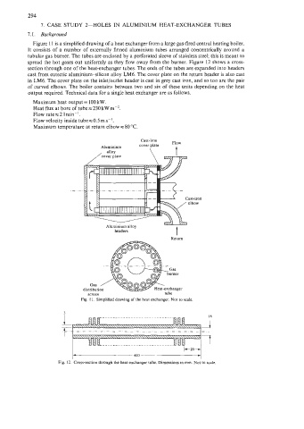
Figure 11 is a simplified drawing of a heat exchanger from a large gas-fired central heating boiler.
It consists of a number of externally finned aluminium tubes arranged concentrically around a
tubular gas burner. The tubes are enclosed by a perforated sleeve of stainless steel; this is meant to
spread the hot gases out uniformly as they flow away from the burner. Figure 12 shows a cross-
section through one of the heat-exchanger tubes. The ends of the tubes are expanded into headers
cast from eutectic aluminium-silicon alloy LM6. The cover plate on the return header is also cast
in LM6. The cover plate on the inlet/outlet header is cast in grey cast iron, and so too are the pair
of curved elbows. The boiler contains between two and six of these units depending on the heat
output required. Technical data for a single heat exchanger are as follows.
Maximum heat output = 100 kW.
Heat flux at bore of tubex230 kW m-*.
Flow rates2 Imin-'.
Flow velocity inside tubes0.5m s-',
Maximum temperature at return elbow = 80 "C.
Cast-iron
Aluminium cover plate
, alloy \ t
/ cover plate \l=zewj
headers
Return
Gas /
distribution
screen tube
Fig. 11. Simplified drawing of the heat exchanger. Not to scale
2
I_ 7
400
Fig. 12. Cross-section through the heat-exchanger tube. Dimensions in mrn. Not to scale.