
Page 367 - Failure Analysis Case Studies II
P. 367
352
the cylinder, but often there is more than one crack observed spaced around the neck. In this study,
two opposed cracks were effectively modelled since a mesh covering one-quarter of the cylinder was
used, which is rather like the situation in Fig. 2. The model contains 800 three-dimensional elements
with mid-nodes and 4098 degrees of freedom. In order to converge the stresses given the singularity
of 1/ Jr at r=O at the crack front, singularity pentahedron elements were employed. This type of
element is obtained by moving the side nodes near the crack tip to the one-quarter position.
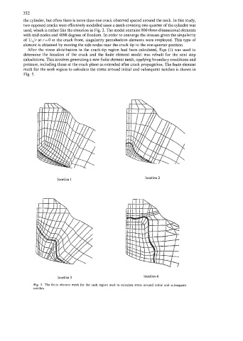
After the stress distribution in the crack-tip region had been calculated, Eqn (1) was used to
determine the location of the crack and the finite element model was rebuilt for the next step
calculations. This involves generating a new finite element mesh, applying boundary conditions and
pressure, including those at the crack plane as extended after crack propagation. The finite element
mesh for the neck region to calculate the stress around initial and subsequent notches is shown in
Fig. 5.
location 1 location 2
location 3 location 4
Fig. 5. The finite element mesh for the neck region used to calculate stress around initial and subsequent
notches.