
Page 368 - Failure Analysis Case Studies II
P. 368
353
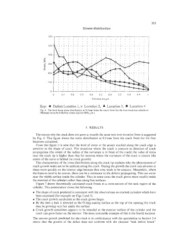
Stress distribution
400
200
100
Key: + Defect Location 1, x Location 2, A Location 3, Location 4
Fig. 6. The local hoop stress distribution at 0.3 mm from the crack front for the four locations calculated
(Multiply stress by 0.0434 to obtain K,(r) in MPaJm.)
5. RESULTS
The reason why the crack does not grow at exactly the same rate over its entire front is suggested
by Fig. 6. This figure shows the stress distribution at 0.3mm from the crack front for the four
locations calculated.
From this figure it is seen that the level of stress at the points marked along the crack edge is
sensitive to the shape of crack. For situations where the crack is concave in direction of crack
propagation (the centre of the radius of the curvature is in front of the crack) the value of stress
near the crack tip is higher than that for sections where the curvature of the crack is convex (the
centre of the curve is behind the crack growth).
This characteristic of the stress distribution along the crack tip explains why the phenomenon of
crack growth tends not to be uniform along the crack. During the growth the crack can advance at
times more quickly on the interior edge because that area tends to be concave. Meanwhile, where
the features tend to be convex, there can be a resistance to the defects propagating. This can occur
near the visible surface inside the cylinder. Thus in some cases the crack grows more readily inside
the material of the cylinder rather than along free surfaces.
Figure 7 shows theoretically calculated crack fronts in a cross-section of the neck region of the
cylinder. This presentation shows the following.
0 The shape of crack predicted is consistent with the observations on cracked cylinders which have
been examined (for example see Figs 2 and 3).
0 The crack growth accelerates as the crack grows larger.
0 By the time a leak is detected at the O-ring mating surface at the top of the opening the crack
may be growing very fast under the surface.
0 Crack growth sometimes appears to be retarded at the exterior surface of the cylinder and the
crack can grow faster on the interior. The most noticeable example of this is the fourth location.
The uneven growth predicted for the crack is in conformance with the speculation in Section 3.4
above that the growth of the defect does not conform with the classical “leak before break”