
Page 590 - Fair, Geyer, and Okun's Water and wastewater engineering : water supply and wastewater removal
P. 590
JWCL344_ch14_500-554.qxd 8/7/10 8:56 PM Page 546
546 Chapter 14 Design of Sewer Systems
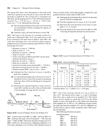
The sewage flow from a new development to the north of the sewers is shown in Fig. 14.26. Pipe lengths, sewage flows, and
trunk line is planned to be conveyed in a new sewer line NB to ground elevations are provided in Table 14.10.
discharge in manhole B. The average flow is estimated to be (a) Determine the total design flow (Q in L/s) in the main
300 Lpcd, and the peaking factor is 3. The following limitations sewer F if line E is running full.
are given: V min 0.75 m/s, V max 3.0 m/s, n 0.013, mini-
mum cover 1.5 m. Determine the following: (b) Find the required sizes for sewers A, B, C, D, and F.
(c) Determine the invert elevations of all sewers at man-
(a) The maximum population that can be served from the
new development without exceeding the capacity of holes 1, 2, 3, 4, 5, and 6.
the trunk sewer (d) Draw the profile for the sewer line from MH 4 to MH
5 showing all important dimensions and elevations.
(b) Diameter, slope, and invert elevations of sewer NB.
14.5 The layout of the last part of a sewerage system for a
small town is illustrated in Fig. 14.25. Two main sewers A and E
B are connected to the trunk sewer at MH 36. After MH 1 the MH 4 MH 3 MH 2 MH 1 MH 5
trunk sewer discharges into a wet well from which sewage is
pumped into the wastewater treatment plant (WWTP). The fol- A B C D
lowing data are known: F
• Diameter of sewer A 800 mm MH 6
• Slope of sewer A 1%
• Diameter of sewer B 500 mm
• Slope of sewer B 0.5%
• Trunk sewer between MH 36 and MH 1 has the same Figure 14.26 Layout of Sanitary Sewers for Problem 14.6.
diameter and slope of sewer A.
• Peak flow in sewer A 850 L/s
• Peak flow in sewer B 150 L/s Table 14.10 Data for Problem 14.6
• Invert level of trunk sewer entering MH 1 510.40 m Ground Elevation
• Elevation of sewage level in wet well 510.00 m Manhole (m)
• Distance between MH 1 and wet well 100 m. Flow Length
Pipe From To (L/s) Upper Lower (m)
(a) Calculate the flow velocities in sewers A and B at
peak flow conditions. E — 1 Full — 612.00 —
(b) At what minimum height above the invert of sewer A A 4 3 20 615.25 613.75 75
should the invert of sewer B be located so that during B 3 2 40 613.75 611.87 75
peak flow, there will be no backing up of sewage into C 2 1 60 611.87 612.00 50
sewer B? D 5 1 17 612.12 612.00 50
F 1 6 Q F 612.00 610.82 100
(c) Determine the required diameter of trunk sewer be-
tween MH 1 and the wet well so that at all times there Conversion factors: 1 m 3.2808 ft; 1 L/s 15.852 gpm.
is free discharge of sewage into the wet well.
14.7 Part of the sewerage network of a city is shown in
Main sewer B
Wet well Fig. 14.27. The lateral sewers (lines 1, 2, and 3) discharge
their flows into a trunk sewer at manhole T11. The lateral
sewers receive sewage at a peak rate of 0.10 L/s per meter
Main
sewer A MH 36 MH 35 MH 1 length of sewer. The peak flow in the trunk sewer upstream
P from manhole T11 is 450 L/s. No additional sewage reaches
the trunk line between manholes T11 and T10. Manholes are
To WWTP located at 65 m center to center on laterals and at 100-m spac-
Trunk sewers ing on trunk lines.
The following elevations are given:
Figure 14.25 Layout of Sanitary Sewers for Problem 14.5.
Ground elevations:
14.6 Lateral sewers from MH 5 to MH 1 and from MH 4 to MH 3 565.50 m
MH 1 intercept the main sewer E (diameter 400 mm and MH 2 565.00 m
slope 0.007) at MH 1. The invert elevation of main sewer E at MH 1 564.25 m
MH 1 is 609.22 m. All sewers have a Manning coefficient, n, of MH T11 563.50 m
0.013 and a minimum cover of 2.00 m. The schematic layout of MH T10 563.00 m