
Page 591 - Fair, Geyer, and Okun's Water and wastewater engineering : water supply and wastewater removal
P. 591
JWCL344_ch14_500-554.qxd 8/7/10 8:56 PM Page 547
Problems/Questions 547
From Table 14.11 Data for Problem 14.8
MH 5 Line 1 MH 4 MH T12
MH Length Ground Level, m Invert Level, m Pipe Dia-
d 200 mm From To m Upper Lower Upper Lower meter, mm
Line 1 d 200 mm Trunk line d 900 mm — 2 — — 405.50 — 403.80 200
...
...
804.98 404.58
...
80
Line 2 Line 2 MH 1 Line 2 2 1 105 1 65 405.50 404.98 ... ... ...
MH T11 — 105 — — 404.58 — 402.18 400
MH 3 MH 2 105 106 100 404.58 404.43 ... ... ...
Line 3 d 200 mm Conversion factors: 1 m 3.2808 ft; 1 mm 0.0394 in.
Line 3 Line 3 Trunk line
d 200 mm d 200 mm profile for the sewers from MH 2 to MH 106 and indicate all
MH 8 MH 7 MH 6 MH T10 ground and invert levels and pipe diameters.
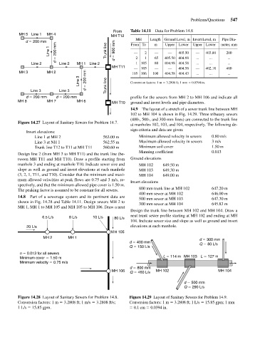
14.9 The layout of a stretch of a sewer trunk line between MH
102 to MH 104 is shown in Fig. 14.29. Three tributary sewers
(400-, 500-, and 300-mm lines) are connected to the trunk line
Figure 14.27 Layout of Sanitary Sewers for Problem 14.7.
at manholes 102, 103, and 104, respectively. The following de-
sign criteria and data are given:
Invert elevations:
Line 1 at MH 2 563.00 m Minimum allowed velocity in sewers 0.80 m/s
Line 3 at NH 1 562.55 m Maximum allowed velocity in sewers 3 m/s
Trunk line T12 to T11 at MH T11 560.60 m Minimum soil cover 1.50 m
Manning coefficient 0.013
Design line 2 (from MH 3 to MH T11) and the trunk line (be-
tween MH T11 and MH T10). Draw a profile starting from Ground elevations
manhole 3 and ending at manhole T10. Indicate sewer size and MH 102 649.50 m
slope as well as ground and invert elevations at each manhole MH 103 649.30 m
(3, 2, 1, T11, and T10). Consider that the minimum and maxi- MH 104 649.00 m
mum allowed velocities at peak flows are 0.75 and 3 m/s, re- Invert elevations
spectively, and that the minimum allowed pipe cover is 1.50 m.
The peaking factor is assumed to be constant for all sewers. 800 mm trunk line at MH 102 647.20 m
400 mm sewer at MH 102 646.00 m
14.8 Part of a sewerage system and its pertinent data are 500 mm sewer at MH 103 647.30 m
shown in Fig. 14.28 and Table 14.11. Design sewers MH 2 to 300 mm sewer at MH 104 645.83 m
MH 1, MH 1 to MH 105 and MH 105 to MH 106. Draw a neat
Design the trunk line between MH 102 and MH 104. Draw a
6.5 L/s 8 L/s 10 L/s 80 L/s neat trunk sewer profile starting at MH 102 and ending at MH
104. Indicate sewer size and slope as well as ground and invert
20 L/s elevations at each manhole.
MH 105
MH 2 MH 1 d 300 mm
d 400 mm Q 80 L/s
Q 150 L/s
n 0.013 for all sewers
Minimum cover 1.50 m L 114 m MH 103 L 127 m
Minimum velocity 0.75 m/s
d 800 mm
MH 106 Q 460 L/s MH 102 MH 104
d 500 mm
Q 290 L/s
Figure 14.28 Layout of Sanitary Sewers for Problem 14.8. Figure 14.29 Layout of Sanitary Sewers for Problem 14.9.
Conversion factors: 1 m 3.2808 ft; 1 m/s 3.2808 ft/s; Conversion factors: 1 m 3.2808 ft; 1 L/s 15.85 gpm; 1 mm
1 L/s 15.85 gpm. 0.1 cm 0.0394 in.