
Page 300 - Fiber Fracture
P. 300
282 J.W.S. Hearle
I
L
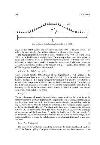
Fig. 15. Lateral elastic buckling, from Hobbs et al. (2000).
under 5% for 40,OOO cycles, and polyester ropes under 10% for 100,OOO cycles. This
reflects the susceptibility of the different fibres to axial compression fatigue.
The theoretical analysis derives from earlier studies (Hobbs, 1984; Hobbs and Liang,
1989) on the buckling of heated pipelines. Thermal expansion causes these to buckle
sinusoidally. Different modes are predicted theoretically: mode 1 with single half-waves
separated by straight zones; mode 2 with one full wave; mode 3 with three half-waves
... continuous (infinite mode). In the notation of Fig. 15, quoting from Hobbs et al.
(2000), the governing differential equation is:
y’+n2y +(m/8)(4x2 - L2) = 0 (2)
where a prime denotes differentiation of the displacement y with respect to the
longitudinal coordinate x, m = pd/EZ and n2 = P/EZ. [p is the radial pressure on a
beam of diameter d.] E is Young’s modulus for the beam, Z its effective second moment
of area, P the compressive axial load and L the buckle half-wavelength. The solution to
this differential equation is presented in Hobbs (1984), but proceeds by considering the
boundary conditions for the various modes, whether localised or periodic, and in each
case gives a relationship of the form:
p = f (L) (3)
The other important element in the analysis is to recognise that as the buckle forms the
force in it drops to maintain displacement compatibility.This equation gives the solution
for the infinite mode, but the localised modes require that the compatibility condition,
Eq. 2, should be modified to include the influence of two ‘slipping lengths’ adjacent
to the localised buckle (Fig. 16). The slip lengths form to accommodate the difference
between PO, the force remotc from the buckle which is unchanged by the formation
of the buckle, and the lower force P, within the buckle itself. The slip length, L,,
is determined by the effective friction between the beam and the surroundings. If the
friction coefficient is p, and the radial pressure p on a beam of diameter d, or perimeter
nd, then:
Ls = (Po - P)/(PPd) (4)
The analysis shows that the controlling features in the elastic buckling of pipelines
are (1) the flexural rigidity of the pipe, (2) the resistance to lateral displacement, (3) the