
Page 102 - Fluid Mechanics and Thermodynamics of Turbomachinery
P. 102
Two-dimensional Cascades 83
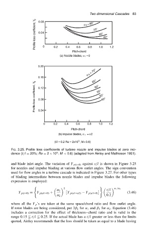
FIG. 3.25. Profile loss coefficients of turbine nozzle and impulse blades at zero inci-
5
dence (t/l D 20%; Re D 2 ð 10 ; M < 0.6) (adapted from Ainley and Mathieson 1951).
and blade inlet angle. The variation of Y p.iD0/ against s/l is shown in Figure 3.25
for nozzles and impulse blading at various flow outlet angles. The sign convention
used for flow angles in a turbine cascade is indicated in Figure 3.27. For other types
of blading intermediate between nozzle blades and impulse blades the following
expression is employed:
( )
2 ˛ 1 /˛ 2
˛ 1 t/l
Y p.iD0/ D Y p.˛1D0/ C Y p.˛1D˛2/ Y p.˛1D0/ (3.46)
˛ 2 0.2
where all the Y p ’s are taken at the same space/chord ratio and flow outlet angle.
If rotor blades are being considered, put 3ˇ 2 for ˛ 1 and ˇ 3 for ˛ 2 . Equation (3.46)
includes a correction for the effect of thickness chord ratio and is valid in the
range 0.15 5 t/l 5 0.25. If the actual blade has a t/l greater or less than the limits
quoted, Ainley recommends that the loss should be taken as equal to a blade having