
Page 169 - Fluid Mechanics and Thermodynamics of Turbomachinery
P. 169
150 Fluid Mechanics, Thermodynamics of Turbomachinery
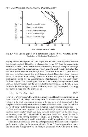
FIG. 5.7. Axial velocity profiles in a compressor (Howell 1945). (Courtesy of the
Institution of Mechanical Engineers).
rapidly thicken through the first few stages and the axial velocity profile becomes
increasingly peaked. This effect is illustrated in Figure 5.7, from the experimental
results of Howell (1945), which shows axial velocity traverses through a four-stage
compressor. Over the central region of the blade, the axial velocity is higher than
the mean value based on the through flow. The mean blade section (and most of
the span) will, therefore, do less work than is estimated from the velocity triangles
based on the mean axial velocity. In theory it would be expected that the tip and
root sections would provide a compensatory effect because of the low axial velocity
in these regions. Due to stalling of these sections (and tip leakage) no such work
increase actually occurs, and the net result is that the work done by the whole blade
is below the design figure. Howell (1945) suggested that the stagnation enthalpy
rise across a stage could be expressed as
h 03 h 01 D U.c y2 c y1 /, (5.29)
where is a “work done”. For multistage compressors Howell recommended for a
mean value of 0.86. Using a similar argument for axial turbines, the increase in axial
velocity at the pitch-line gives an increase in the amount of work done, which is then
roughly cancelled out by the loss in work done at the blade ends. Thus, for turbines,
no “work done” factor is required as a correction in performance calculations.
Other workers have suggested that should be high at entry (0.96) where the
annulus wall boundary layers are thin, reducing progressively in the later stages
of the compressor (0.85). Howell (1950) has given mean “work done” factors for
compressors with varying numbers of stages, as in Figure 5.9. For a four-stage
compressor the value of would be 0.9 which would be applied to all four stages.
Smith (1970) commented upon the rather pronounced deterioration of compressor
performance implied by the example given in Figure 5.7 and suggested that things
are not so bad as suggested. As an example of modern practice he gave the axial