
Page 174 - Fluid Mechanics and Thermodynamics of Turbomachinery
P. 174
Axial-flow Compressors and Fans 155
FIG. 5.10. Compressor stall inception (adapted from Greitzer et al. 1979).
Rotor blade
B
A A
Section
Flow Rotor Casing B-B
blade treatment
insert
B
0 3 cm
Rotation
60°
(a) Section A-A
(b)
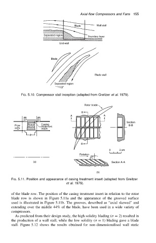
FIG. 5.11. Position and appearance of casing treatment insert (adapted from Greitzer
et al. 1979).
of the blade row. The position of the casing treatment insert in relation to the rotor
blade row is shown in Figure 5.11a and the appearance of the grooved surface
used is illustrated in Figure 5.11b. The grooves, described as “axial skewed” and
extending over the middle 44% of the blade, have been used in a wide variety of
compressors.
As predicted from their design study, the high solidity blading ( D 2) resulted in
the production of a wall stall, while the low solidity ( D 1) blading gave a blade
stall. Figure 5.12 shows the results obtained for non-dimensionalised wall static