
Page 231 - Fluid Mechanics and Thermodynamics of Turbomachinery
P. 231
212 Fluid Mechanics, Thermodynamics of Turbomachinery
Use of prewhirl at entry to impeller
Introducing positive prewhirl (i.e. in the direction of impeller rotation) can give a
significant reduction of the inlet Mach number M r1 but, as seen from eqn. (2.12c),
it reduces the specific work done on the gas. As will be seen later, it is necessary
to increase the blade tip speed to maintain the same level of impeller pressure ratio
as was obtained without prewhirl.
Prewhirl is obtained by fitting guide vanes upstream of the impeller. One arrange-
ment for doing this is shown in Figure 7.5a. The velocity triangles, Figure 7.5b
and c, show how the guide vanes reduce the relative inlet velocity. Guide vanes are
designed to produce either a free-vortex or a forced-vortex velocity distribution. In
Chapter 6 it was shown that for a free-vortex flow the axial velocity c x is constant
(in the ideal flow) with the tangential velocity c varying inversely with the radius.
It was shown by Wallace et al. (1975) that the use of free-vortex prewhirl vanes
leads to a significant increase in incidence angle at low inducer radius ratios. The
use of some forced-vortex velocity distribution does alleviate this problem. Some of
the effects resulting from the adoption of various forms of forced-vortex of the type
n
r
c D A
r s1
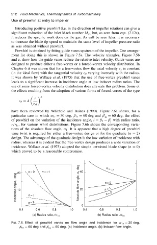
have been reviewed by Whitfield and Baines (1990). Figure 7.6a shows, for a
0
particular case in which ˛ 1s D 30 deg, ˇ 1s D 60 deg and ˇ D 60 deg, the effect
1s
0
ˇ with radius ratio,
of prewhirl on the variation of the incidence angle, i D ˇ 1
1
r/r 1s , for various whirl distributions. Figure 7.6b shows the corresponding varia-
tions of the absolute flow angle, ˛ 1 . It is apparent that a high degree of prewhirl
vane twist is required for either a free-vortex design or for the quadratic (n D 2)
design. The advantage of the quadratic design is the low variation of incidence with
radius, whereas it is evident that the free-vortex design produces a wide variation of
incidence. Wallace et al. (1975) adopted the simple untwisted blade shape (n D 0)
which proved to be a reasonable compromise.
n = -
1
0
Incidence angle, i deg 20 n = n = - Absolute flow angle, a 1 deg 40 n = 1
0
n = 1
20
10
n = 2
n = 1
n = 2
0
0.4 0.6 0.8 1.0 0.4 0.6 0.8 1.0
(a) Radius ratio, r/r 1s (b) Radius ratio, r/r 1s
FIG. 7.6. Effect of prewhirl vanes on flow angle and incidence for ˛ 1s D 30 deg,
ˇ 1s D 60 deg and ˇ 0 D 60 deg. (a) Incidence angle. (b) Inducer flow angle.
1s