Page 229 - Fluid Mechanics and Thermodynamics of Turbomachinery
P. 229

210 Fluid Mechanics, Thermodynamics of Turbomachinery


                                              M r1  =  0.9                             a 1
                              0.4                       A                              C 1
                                                                                      b
                                                                                       1   U
                                     a  = 30˚    0.8                                        1
                                      1                                               W
                            k p 01   01 3 )  a                B                       At A
                              0.3
                                                                                       1
                            ¦ (M r1 ) =  mW 2 /(p       0.8                              C 1

                           ·  0.2                     0.9


                                           0˚
                                         1
                              0.1       a  =                                           b 1
                                                                                      W    U
                                                                                       1    1

                               0
                               10     20    30    40     50    60    70    80         At B
                                         Relative flow angle at shroud, b 1 , deg

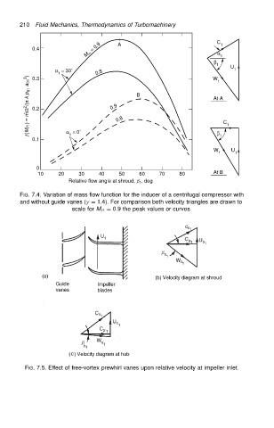
                          FIG. 7.4. Variation of mass flow function for the inducer of a centrifugal compressor with
                          and without guide vanes (
 D 1.4). For comparison both velocity triangles are drawn to
                                          scale for M r1 D 0.9 the peak values or curves.


                           FIG. 7.5. Effect of free-vortex prewhirl vanes upon relative velocity at impeller inlet.
   224   225   226   227   228   229   230   231   232   233   234