
Page 232 - Fluid Mechanics and Thermodynamics of Turbomachinery
P. 232
Centrifugal Pumps, Fans and Compressors 213
Slip factor
Introduction
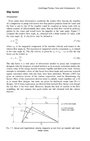
Even under ideal (frictionless) conditions the relative flow leaving the impeller
of a compressor or pump will receive less than perfect guidance from the vanes and
the flow is said to slip. If the impeller could be imagined as being made with an
infinite number of infinitesimally thin vanes, then an ideal flow would be perfectly
guided by the vanes and would leave the impeller at the vane angle. Figure 7.7
compares the relative flow angle, ˇ 2 , obtained with a finite number of vanes, with
0
the vane angle, ˇ .A slip factor may be defined as
2
c 2
D 0 , (7.13a/
c
2
where c 2 is the tangential component of the absolute velocity and related to the
relative flow angle ˇ 2 . The hypothetical tangential velocity component c 0 2 is related
0
to the vane angle ˇ . The slip velocity is given by c s D c 0 c 2 so that the slip
2 2
factor can be written as
c s
D 1 . (7.13b/
c 0
2
The slip factor is a vital piece of information needed by pump and compressor
designers (also by designers of radial turbines) as its accurate estimation enables the
correct value of the energy transfer between impeller and fluid to be made. Various
attempts to determine values of slip factor have been made and numerous research
papers concerned solely with this topic have been published. Wiesner (1967) has
given an extensive review of the various expressions used for determining slip
0
factors. Most of the expressions derived relate to radially vaned impellers (ˇ D 0)
2
or to mixed flow designs, but some are given for backward swept vane (b s v)
designs. All of these expressions are derived from inviscid flow theory even though
the real flow is far from ideal. However, despite this lack of realism in the flow
modelling, the fact remains that good results are still obtained with the various
theories.
C ¢ q2
C q2
C qs b 2 ¢ is the vane angle
b 2 is the average
b ¢ 2 relative flow angle
b 2 C 2
C r2
W 2
U 2
FIG. 7.7. Actual and hypothetical velocity diagrams at exit from an impeller with back
swept vanes.