Page 228 - Fluid Mechanics and Thermodynamics of Turbomachinery
P. 228

Centrifugal Pumps, Fans and Compressors  209
                          where
                                0 D p 0 /.RT 0 /.

                            The absolute Mach number M 1 and the relative Mach number M r1 are defined as

                              M 1 D c x1 /a 1 D M r1 cos ˇ s1 and w s1 D M r1 a 1 .
                            Using these relations together with eqn. (7.10)
                                 2                 3  3
                               P m RT 01        M a
                                                   r1 1          2
                                                               sin ˇ s1 cos ˇ s1
                                       D                  1/.y 1/
                                          1 C .
   1/M
                                k p 01        1        2
                                              2        1
                                            1           1/2
                          Since a 01 /a 1 D 1 C .
  1/M 2  and a 01 D .
RT 01 / 1/2  the above equation is
                                            2        1
                          rearranged to give
                                    P m 2                3   2
                                                        M sin ˇ s1 cos ˇ s1
                                                          r1                              (7.11)
                               k
p 01 .
RT 01 / 1/2  D   1 C .
  2  2    1/.
 1/C3/2
                                                     1
                                                              r1
                                                     2    1/M cos ˇ s1
                          This equation is extremely useful and can be used in a number of different ways.
                          For a particular gas and known inlet conditions one can specify values of 
, R, p 01
                                             2
                          and T 01 and obtain Pm /k as a function of M r1 and ˇ s1 . By specifying a particular
                          value of M r1 as a limit, the optimum value of ˇ s1 for maximum mass flow can be
                          found. A graphical procedure is the simplest method of optimising ˇ s1 as illustrated
                          below.
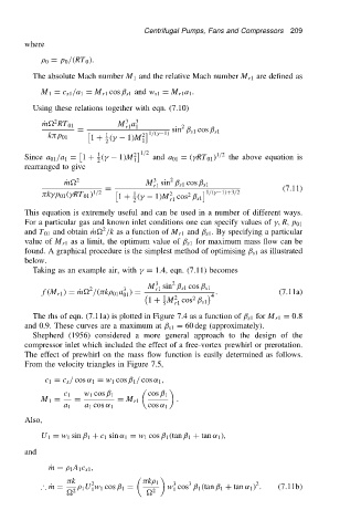
                            Taking as an example air, with 
 D 1.4, eqn. (7.11) becomes
                                                          3    2
                                          2       3      M sin ˇ s1 cos ˇ s1
                                                          r1
                              f.M r1 / DPm /. k  01 a / D               .               (7.11a)
                                                  01
                                                                        4
                                                            1  2    2
                                                         1 C M cos ˇ s1
                                                               r1
                                                            5
                            The rhs of eqn. (7.11a) is plotted in Figure 7.4 as a function of ˇ s1 for M r1 D 0.8
                          and 0.9. These curves are a maximum at ˇ s1 D 60 deg (approximately).
                            Shepherd (1956) considered a more general approach to the design of the
                          compressor inlet which included the effect of a free-vortex prewhirl or prerotation.
                          The effect of prewhirl on the mass flow function is easily determined as follows.
                          From the velocity triangles in Figure 7.5,
                               c 1 D c x / cos ˛ 1 D w 1 cos ˇ 1 / cos ˛ 1 ,

                                    c 1  w 1 cos ˇ 1     cos ˇ 1
                              M 1 D   D          D M r1         .
                                    a 1  a 1 cos ˛ 1     cos ˛ 1
                          Also,
                              U 1 D w 1 sin ˇ 1 C c 1 sin ˛ 1 D w 1 cos ˇ 1 .tan ˇ 1 C tan ˛ 1 /,
                          and

                                P m D   1 A 1 c x1 ,

                                     k    2             k  1   3   3                2
                              ∴ Pm D     1 U w 1 cos ˇ 1 D   w cos ˇ 1 .tan ˇ 1 C tan ˛ 1 / .  .7.11b/
                                          1
                                                               1
                                     2                  2
   223   224   225   226   227   228   229   230   231   232   233