Page 230 - Fluid Mechanics and Thermodynamics of Turbomachinery
P. 230

Centrifugal Pumps, Fans and Compressors  211
                          Thus, using the relations developed earlier for T 01 /T 1 ,p 01 /p 1 and   01 /  1 , we obtain
                                                             3
                                                         3
                                         P m 2        M cos ˇ 1 .tan ˇ 1 C tan ˛ 1 / 2
                                                         r1
                              f.M r1 / D     3  D                                  3  .   (7.12)
                                        k  01 a 01     
   1                   1  C  2
                                                                              
 1
                                                              2
                                                                  2
                                                                          2
                                                   1 C      M cos ˇ 1 / cos ˛ 1
                                                              r1
                                                         2
                          Substituting 
 D 1.4 for air into eqn. (7.12) we get:
                                           2
                                                        3
                                                    3
                                          Pm     M cos ˇ 1 .tan ˇ 1 C tan ˛ 1 / 2
                                                    r1
                              f.M r1 / D       D                          .              (7.12a)
                                        k  01 a 3     1  2    2      2   4
                                             01    1 C M cos ˇ 1 / cos ˛ 1
                                                      5  r1
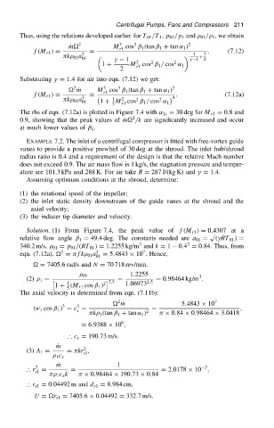
                          The rhs of eqn. (7.12a) is plotted in Figure 7.4 with ˛ 1s D 30 deg for M r1 D 0.8 and
                                                             2
                          0.9, showing that the peak values of Pm /k are significantly increased and occur
                          at much lower values of ˇ 1 .
                            EXAMPLE 7.2. The inlet of a centrifugal compressor is fitted with free-vortex guide
                          vanes to provide a positive prewhirl of 30 deg at the shroud. The inlet hub/shroud
                          radius ratio is 0.4 and a requirement of the design is that the relative Mach number
                          does not exceed 0.9. The air mass flow is 1 kg/s, the stagnation pressure and temper-
                          ature are 101.3 kPa and 288 K. For air take R D 287 J/(kg K) and 
 D 1.4.
                            Assuming optimum conditions at the shroud, determine:
                          (1) the rotational speed of the impeller;
                          (2) the inlet static density downstream of the guide vanes at the shroud and the
                             axial velocity;
                          (3) the inducer tip diameter and velocity.
                            Solution. (1) From Figure 7.4, the peak value of f.M r1 / D 0.4307 at a
                                                                                     p
                          relative flow angle ˇ 1 D 49.4 deg. The constants needed are a 01 D  .
RT 01 / D
                                                               3
                                                                              2
                          340.2 m/s,   01 D p 01 /.RT 01 / D 1.2255 kg/m and k D 1  0.4 D 0.84. Thus, from
                                                                7
                                       2
                          eqn. (7.12a),  D  fk  01 a 3  D 5.4843 ð 10 . Hence,
                                                 01
                               D 7405.6 rad/s and N D 70 718 rev/min.
                                                            1.2255
                                              01                                 3
                                                        D           D 0.98464 kg/m .
                            (2)   1 D    1            2.5        2.5
                                     1 C .M r1 cos ˇ 1 / 2  1.06973
                                        5
                          The axial velocity is determined from eqn. (7.11b):
                                                        2
                                                        Pm                 5.4843 ð 10 7
                                           3
                                       3
                              .w 1 cos ˇ 1 / D c D                 D                          ,
                                           x                     2
                                                k  1 .tan ˇ 1 C tan ˛ 1 /    ð 0.84 ð 0.98464 ð 3.0418
                                                         6
                                             D 6.9388 ð 10 ,
                                         ∴ c x D 190.73 m/s.
                                     P m
                                              2
                            (3) A 1 D   D  kr ,
                                              s1
                                      1 c x
                                      P m               1                          3
                               2
                            ∴ r D         D                           D 2.0178 ð 10 ,
                               s1
                                      1 c x k    ð 0.98464 ð 190.73 ð 0.84
                            ∴ r s1 D 0.04492 m and d s1 D 8.984 cm,
                              U D r s1 D 7405.6 ð 0.04492 D 332.7 m/s.
   225   226   227   228   229   230   231   232   233   234   235