Page 242 - Fluid Mechanics and Thermodynamics of Turbomachinery
P. 242

Centrifugal Pumps, Fans and Compressors  223

                                           1   2    2   1  2    2
                                      h 1 D  .U   U / C .w     w /,
                                  h 2          2    1      1    2
                                           2            2
                                                1  2  1  2    1  2    2        1   2    2
                                    ∴ h 2 D .h 1 C w 1  U / C .U 2  w / D h 01 C .U 2  w /
                                                         1
                                                                      2
                                                                                        2
                                                2     2       2                2
                          hence,

                                                      2
                                                  2
                                                U    w                        w 2
                                     T 2          2   2                2       2
                                         D 1 C  2        D 1 C .
   1/M u  1   2  ,       .7.27/
                                     T 01      a / .
  1/                     U
                                                01                             2
                                             2
                          since h 01 D C p T 01 D a /.
  1/.
                                             01
                            From the exit velocity triangle, Figure 7.7,
                                     2    2            2   2           0  2
                                    w D c C .U 2   c  2 / D c C .U 2   c /
                                     2    r2               r2           2
                                          2                      0  2
                                       D c C [U 2   .U 2  c r2 tan ˇ /] ,
                                          r2
                                                                 2
                                      2
                                 w 2          2                  0  2
                            1          D 1       [1   .1     2 tan ˇ /] .                 .7.28/
                                              2                  2
                                 U 2
                          Substituting eqns. (7.26), (7.27) and (7.28) into eqn. (7.25), we get:
                                               h                2   i
                                            M 2    2  1    2 tan ˇ 0  C   2
                                2            u               2     2
                              M D                                           .             (7.29)
                                2
                                                                           2
                                       1
                                                 2
                                                                         0
                                    1 C .
   1/ M f1    2  1   .1    2 tan ˇ / g
                                       2         u     2                 2
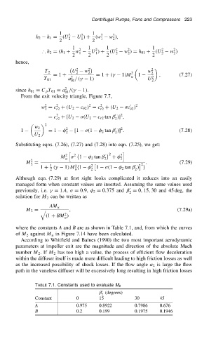
                          Although eqn. (7.29) at first sight looks complicated it reduces into an easily
                          managed form when constant values are inserted. Assuming the same values used
                                                                       0
                          previously, i.e. 
 D 1.4,   D 0.9,   2 D 0.375 and ˇ D 0, 15, 30 and 45 deg, the
                                                                      2
                          solution for M 2 can be written as
                                       AM u
                                               ,                                         (7.29a)
                              M 2 D q
                                             2
                                      .1 C BM /
                                             u
                          where the constants A and B are as shown in Table 7.1, and, from which the curves
                          of M 2 against M u in Figure 7.14 have been calculated.
                            According to Whitfield and Baines (1990) the two most important aerodynamic
                          parameters at impeller exit are the magnitude and direction of the absolute Mach
                          number M 2 .If M 2 has too high a value, the process of efficient flow deceleration
                          within the diffuser itself is made more difficult leading to high friction losses as well
                          as the increased possibility of shock losses. If the flow angle ˛ 2 is large the flow
                          path in the vaneless diffuser will be excessively long resulting in high friction losses
                                 TABLE 7.1. Constants used to evaluate M 2
                                                            0
                                                           ˇ (degrees)
                                                            2
                                 Constant         0        15            30       45
                                 A                0.975    0.8922        0.7986   0.676
                                 B                0.2      0.199         0.1975   0.1946
   237   238   239   240   241   242   243   244   245   246   247