
Page 247 - Fluid Mechanics and Thermodynamics of Turbomachinery
P. 247
228 Fluid Mechanics, Thermodynamics of Turbomachinery
1
the absolute flow angle ˛ 2 D tan .c /c r / is also constant as the fluid is diffused
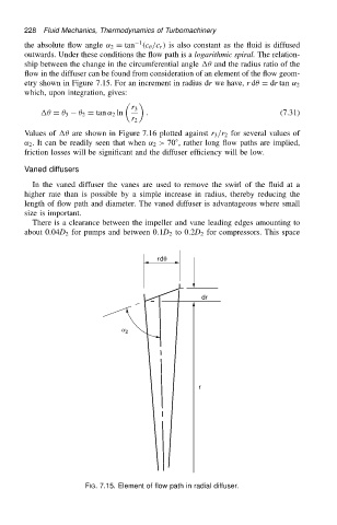
outwards. Under these conditions the flow path is a logarithmic spiral. The relation-
ship between the change in the circumferential angle and the radius ratio of the
flow in the diffuser can be found from consideration of an element of the flow geom-
etry shown in Figure 7.15. For an increment in radius dr we have, r d D dr tan ˛ 2
which, upon integration, gives:
r 3
D 3 2 D tan ˛ 2 ln . (7.31)
r 2
Values of are shown in Figure 7.16 plotted against r 3 /r 2 for several values of
˛ 2 . It can be readily seen that when ˛ 2 > 70 ° , rather long flow paths are implied,
friction losses will be significant and the diffuser efficiency will be low.
Vaned diffusers
In the vaned diffuser the vanes are used to remove the swirl of the fluid at a
higher rate than is possible by a simple increase in radius, thereby reducing the
length of flow path and diameter. The vaned diffuser is advantageous where small
size is important.
There is a clearance between the impeller and vane leading edges amounting to
about 0.04D 2 for pumps and between 0.1D 2 to 0.2D 2 for compressors. This space
rdq
dr
a 2
r
FIG. 7.15. Element of flow path in radial diffuser.