
Page 244 - Fluid Mechanics and Thermodynamics of Turbomachinery
P. 244
Centrifugal Pumps, Fans and Compressors 225
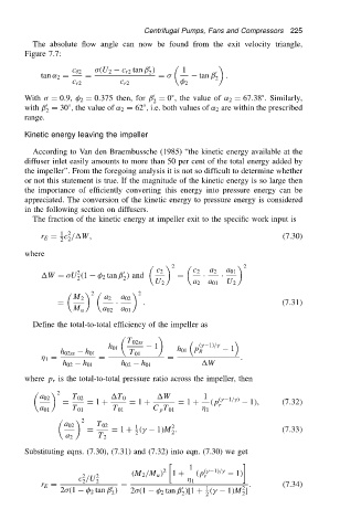
The absolute flow angle can now be found from the exit velocity triangle,
Figure 7.7:
0
c r2 tan ˇ / 1
c 2 .U 2 2 0
tan ˛ 2 D D D tan ˇ .
2
c r2 c r2 2
0
With D 0.9, 2 D 0.375 then, for ˇ D 0 ° , the value of ˛ 2 D 67.38 ° . Similarly,
2
0
with ˇ D 30 ° , the value of ˛ 2 D 62 ° , i.e. both values of ˛ 2 are within the prescribed
2
range.
Kinetic energy leaving the impeller
According to Van den Braembussche (1985) “the kinetic energy available at the
diffuser inlet easily amounts to more than 50 per cent of the total energy added by
the impeller”. From the foregoing analysis it is not so difficult to determine whether
or not this statement is true. If the magnitude of the kinetic energy is so large then
the importance of efficiently converting this energy into pressure energy can be
appreciated. The conversion of the kinetic energy to pressure energy is considered
in the following section on diffusers.
The fraction of the kinetic energy at impeller exit to the specific work input is
1 2
r E D c /W, (7.30)
2 2
where
2 2
0
2
W D U .1 2 tan ˇ / and c 2 D c 2 Ð a 2 Ð a 01
2 2
U 2 a 2 a 01 U 2
2
2
M 2 a 2 a 02
D Ð . .7.31/
M u a 02 a 01
Define the total-to-total efficiency of the impeller as
T 02ss
h 01 1 h 01 p .
1//
1
h 02ss h 01 T 01 R
1 D D D .
h 02 h 01 h 02 h 01 W
where p r is the total-to-total pressure ratio across the impeller, then
2
a 02 T 02 T 0 W 1 .
1/
/
D D 1 C D 1 C D 1 C .p 1/, .7.32/
r
a 01 T 01 T 01 C p T 01 1
2
a 02 T 02 1 2
D D 1 C .
1/M . .7.33/
2 2
a 2 T 2
Substituting eqns. (7.30), (7.31) and (7.32) into eqn. (7.30) we get
1 .
1//
2
.M 2 /M u / 1 C .p 1/
2
c /U 2 2 1 r
2
r E D 0 D 1 . (7.34)
2
0
2 .1 2 tan ˇ / 2 .1 2 tan ˇ /[1 C .
1/M ]
2 2 2 2