
Page 280 - Fluid mechanics, heat transfer, and mass transfer
P. 280
CONVECTIVE HEAT TRANSFER 261
X
1=U ¼ 1=h o þ 1=h i þ ðmetal wall and fouling foreign solid material (fouling deposit) inside the
tube, metal wall, deposits of foreign solid material
resistances on both sides of the metal wallÞ:
outside the tube, and outside fluid film. Resistances
ð9:43Þ due to deposits are significantly high due to low
thermal conductivities of these deposit materials.
& If the inside and outside surfaces are clean, fouling
These resistances are lumped into what are known as
resistances will be zero. Generally, metal wall resis-
fouling factors that depend on nature, thicknesses,
tance can be assumed to be negligible, metals being
average thermal conductivities, structure, and
good conductors of heat. In such a case, the equation
porosities of the deposits.
reduces to the form
& Fouling factors contribute to decrease of heat transfer
rates.
1=U ¼ 1=h o þ 1=h i : ð9:44Þ
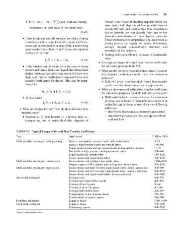
. Give typical ranges of overall heat transfer coefficients
& If the outside fluid is steam as in the case of steam for the cases given in Table 9.3.
heaters and inside fluid is oil, liquid film offers much . What are the normally recommended values of overall
higher resistance as condensing steam will have very heat transfer coefficients to be used for estimation
high heat transfer coefficients compared to the heat purposes?
transfer coefficients for the oil. This can be repre- & Table 9.4 gives recommended overall heat transfer
sented by coefficients for broad categories of applications.
. What are the sources of getting heat transfer coefficients
h o h i or 1=h o ¼ 1=h i :
for estimation purposes for shell and tube exchangers?
& In such cases, & Shell and tube heat transfer coefficient for estimation
purposes can be found in many reference books or an
1=U 1=h o or U h o : ð9:45Þ
online list can be found at one of the two following
. What are fouling factors? How do they influence heat addresses:
transfer rates? ➢ http://www.cheresources.com/uexchangers.shtml
& Resistances to heat transfer in a tubular heat ex- ➢ http://www.processassociates.com/process/heat/
changer are due to inside fluid film, deposits of uvalues1.htm
TABLE 9.3 Typical Ranges of Overall Heat Transfer Coefficients
2
Type Application U (W/(m K))
Shell and tube exchanger: heating/cooling Gases at atmospheric pressure inside and outside tubes 5–35
Gases at high pressure inside and outside tubes 150–500
Liquid inside/outside and gas outside/inside at atmospheric pressure 15–70
Gas inside at high pressure and liquid outside tubes 200–400
Liquid inside and outside tubes 150–1200
Steam outside and liquid inside tubes 300–1200
Shell and tube exchanger: condensation Steam outside and cooling water inside tubes 1500–4000
Organic vapors or NH 3 outside and cooling water inside tubes 300–1200
Shell and tube exchanger: vaporization Steam outside and high-viscosity liquid inside tubes: natural circulation 300–900
Steam outside and low-viscosity liquid inside tubes: natural circulation 600–1700
Steam outside and liquid inside tubes: forced circulation 900–3000
Air-cooled exchanger Cooling water 600–750
Cooling light hydrocarbon liquids 400–550
Cooling of tarry liquids 30–60
Cooling of air or flue gases 60–180
Cooling hydrocarbon gases 200–450
Condensation of low-pressure steam 700–850
Condensation of organic vapors 350–500
Plate heat exchanger Liquid to liquid 1000–4000
Spiral heat exchanger Liquid to liquid 700–2500
Condensing vapors 900–3500
Source: cheresources.com.