
Page 281 - Fluid mechanics, heat transfer, and mass transfer
P. 281
CONVECTIVE HEAT TRANSFER BASICS
262
➢ Low thermal diffusivity.
TABLE 9.4 Recommended U for Broad Categories of
➢ Low freezing point (at least 20 C lower than the
Design Applications
Category W/(m C) lowest operating temperature) to avoid freezing on
2
the heat transfer surfaces.
Water–liquid 850
Liquid–liquid 280 ➢ High flash point and high self-ignition tempera-
Liquid–gas 60 tures making it less susceptible to ignition.
Gas–gas 30 ➢ From ignition point of view, not only flash point
Reboilers 1140 and self-ignition temperature but also tendency for
formation of aerosols during use of heat transfer
fluids is an important criterion. The following four
& Annexure gives typical ranges of heat transfer
properties/conditions of the heat transfer fluids
coefficients that can be used in the preliminary influence this tendency:
design of heat transfer equipment in different - Higher density fluids tend to form smaller dro-
refinery units. plets upon leaking.
. Give an estimation method for overall heat transfer - Higher viscosity fluids are less likely to form an
coefficients for use in preliminary design of heat aerosol.
exchangers. - Higher surface tension fluids will form larger
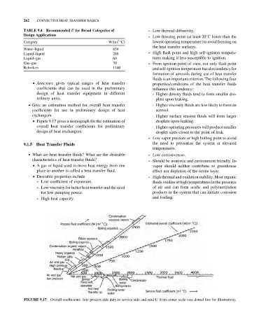
& Figure 9.17 gives a nomograph for the estimation of droplets upon leaking.
overall heat transfer coefficients for preliminary - Higher operating pressures will produce smaller
design of heat exchangers. droplet sizes closer to the point of leak.
➢ Low vapor pressure or high boiling point to avoid
the need to pressurize the system at elevated
9.1.5 Heat Transfer Fluids
temperatures.
. What are heat transfer fluids? What are the desirable ➢ Low corrosiveness.
characteristics of heat transfer fluids? ➢ Should be nontoxic and environment friendly. Its
& A gas or liquid used to move heat energy from one vapor should neither contribute to greenhouse
place to another is called a heat transfer fluid. effect nor depletion of the ozone layer.
& Desirable properties include ➢ High thermal and oxidation stability. Most organic
➢ Low coefficient of expansion. fluids oxidize at high temperatures in the presence
➢ Low viscosity for better heat transfer and the need of air and can form acidic and polymerization
for low pumping power. products in the system that can initiate corrosion
➢ High heat capacity. and fouling.
Overall coefficients. Join process side duty to service side and read U from center scale (see dotted line for illustration).
FIGURE 9.17