
Page 279 - Fluid mechanics, heat transfer, and mass transfer
P. 279
CONVECTIVE HEAT TRANSFER BASICS
260
& U is commonly referred to A o , the total outside tube
TABLE 9.1 Magnitude of Heat Transfer Coefficients in
heat transfer area, including fins (if any).
Increasing Order are Illustrated
Given Order Correct Order & Mean wall heat transfer area A m is given by
Heating/cooling of oils Heating/cooling of air/gases
A m ¼ pLðD i þ D o Þ=2: ð9:40Þ
Boiling water Desuperheating steam
Dropwise condensation of 30% NaOH solution
& If U i , based on inside heat transfer area, is preferred
steam
over U o , the following relationship holds:
Film condensation of steam Heating/cooling of oils
Condensation of steam Heating/cooling of water
containing air U o A o ¼ U i A i or U o =U i ¼ A i =A o ¼ D i =D o : ð9:41Þ
Desuperheating steam Condensation of steam
& Identification of the reference area, that is, whether
containing air
Heating/cooling of water Boiling water the heat transfer coefficient is based on the outside or
Heating/cooling of air/gases Film condensation of steam inside surface area, should be specified.
30% NaOH solution Dropwise condensation of
U o 6¼ U i ; unless A o ¼ A i : ð9:42Þ
steam
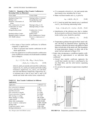
& Temperature gradients through hot fluid, metal wall,
and cold fluid are illustrated below, signifying the
. Give ranges of heat transfer coefficients for different
resistances offered by the metal wall and the two fluid
categories of applications.
films on both sides of the metal wall. The boundaries
& Table 9.2 presents heat transfer coefficients for dif-
of steep temperature changes on either side of the
ferent applications. metal wall are indicated in Figure 9.16.
. Give the equation for overall heat transfer coefficient in . Under what circumstances overall heat transfer coeffi-
terms of different resistances for heat transfer in tubular
cient can be approximated to an individual film
heat exchangers.
coefficient?
& Overall heat transfer coefficient represents the
U o ¼ 1=½1=h o þ R fo þ R fins þ Dx w A o =k w A m
overall heat transfer rate that is contributed by the
þ R fi A o =A i þ 1=h i A o =A i ; ð9:39Þ two fluid films, and the solid barriers separating
the fluids.
where h o and h i are outside and inside filmcoefficients,
& It is given by the equation in approximate simplified
respectively; R fo and R fi are outside and inside fouling
form:
resistances, respectively; Dx w and k w are wall thick-
ness and wall thermal conductivity, respectively; R fins
is resistance due to fins (if any); and A o and A i are
outside and inside tube surface areas, respectively.
TABLE 9.2 Heat Transfer Coefficients for Different
Applications
2
Application h (W/(m C))
Free convection in air/gases 1–50
Forced convection in gases 25–250
Superheated steam 30–100
Free convection in liquids 10–1,000
Forced convection in liquids 50–20,000
Oils: heating or cooling 50–1,500
Water: heating or cooling 300–20,000
Liquid metals 5,000–250,000
Steam: film condensation 6,000–20,000
Steam: dropwise condensation 30,000–100,000
Boiling water 1,700–50,000
Condensing organic vapors 1,000–2000
Boiling/condensation 2,500–100,000
Note: Ranges taken from different sources. FIGURE 9.16 Temperature gradients in forced convection.